Transcription of Series MS Magnesense Differential Pressure Transmitter
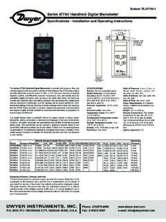
1 DWYER INSTRUMENTS, : 219 Box 373 Michigan City, IN 46361-0373, : 219/872-9057e-mail: Series MS Magnesense Differential Pressure Transmitteris anextremely versatile Transmitter for monitoring Pressure and air compact package is loaded with features such as: field selectableEnglish or metric ranges, field upgradeable LCD display and the abilityto select a square root output for use with pitot tubes and other similarflow sensors. Also, a single digital push button simultaneously calibratesboth zero and span reducing installation and setup time. These featuresalong with exceptional long term performance enables the Magnesense to be the solution for a myriad of Pressure and air flow applications.
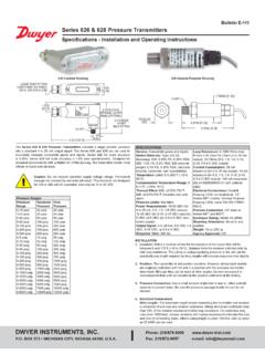
2 INSTALLATIONM ounting: The Transmitter should be mounted on a vertical surface with theconnections directed down to prevent moisture from entering either thepressure ports or the electrical cable the Transmitter using #8 x 1/2 pan head sheet metal screws in themounting flanges. Do not over tighten. Electrical Connection:2-Wire Operation: Series MS Magnesense Differential Pressure TransmitterSpecifications - Installation and Operating InstructionsBulletin A-26 PSPECIFICATIONSS ervice:Air and non-combustible, compatible gases. Wetted Materials:Consult : 1% @ standard : 1% Limits:0 to 150 F (-18 to 66 C). Pressure Limits:1 psi ( kPa) maximum, operation; 10 psi ( kPa), Requirements:2-wire, 10 to 35 VDC; 3-wire, 17 to 36 VDC or isolated to 33 Signals:2-wire, 4 to 20 mA; 3-wire, 0 to 10 V or 0 to 5 V.
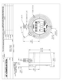
3 Response Time:300 Calibration:One digital push button set both zero & Resistance:Current output: 0 to 1250 ohm max.; Voltage output: min. load resistance 1 k ohm .Current Consumption:40 mA (optional):4 digit Connections:4 to 20 mA units: 2-wire: European style terminal block for 16 to 26 AWG; 0 to 10 V units: 3-wire: European style terminal block 16 to 22 Entry:1/2 NPS thread. Accessory: A-151 cable gland for 5 to 10 mm diameter Connections:3/16 (5 mm) ID tubing. Maximum OD 9 Rating:NEMA 4X (IP65).Mounting Orientation:Insensitive to mounting : oz (230 g).Agency following standards were used for CE approval:CENELEC EN 61000-4-2: 2001 CENELEC EN 61000-4-3: 2002 CENELEC EN 61000-4-4: 1995 CENELEC EN 61000-4-5: 2001 CENELEC EN 61000-4-6: 2003 CENELEC EN 61000-4-8: 2001 CENELEC EN 55011: 2003 CENELEC EN 61326: 200289/336/EED EMC Directive 3-7/16[ ]2-41/64[ ]1/2 NPT21/32[ ]21/32[ ]29/32[ ]1/2[ ]57/64[ ](3) 3/16 [ ] HOLESEQUALLY SPACED ON [ ] BC2-11/64[ ]2-9/16[ ]DO NOT EXCEED SPECIFIED SUPPLY VOLTAGERATINGS.
4 PERMANENT DAMAGE NOT COVERED BYWARRANTY WILL RESULT. 2-WIRE UNITS ARE NOT DESIGNED FOR ACVOLTAGE 3-7/16[ ]1/2 NPT25/64[ ]1-41/64[ ]2-41/64[ ]21/32[ ]57/64[ ]21/32[ ]29/32[ ]1/2[ ]2-11/64[ ]3-11/32[ ]3-1/2[ ]Wall Mount BracketDIN Mount BracketA-26P: Magnesense bulletin 2/21/11 12:13 PM Page 1 Electrical Connection:2-Wire Operation, continued:The connections to the Transmitter are made through a two circuitEuropean style terminal block CONN6 located at the bottom of the mainPCB board. Polarity is indicated by + and signs on the PCB board. Donot connect to the (V) 1An external power supply delivering 10 to 35 VDC with a minimumcurrent capability of 40 milliamps must be used to power the control loopin which the Magnesense Transmitter is connected.
5 Refer to Fig. 1 forconnection of the power supply, Transmitter and receiver. The range ofappropriate receiver load resistances (RL) for the power supply voltageavailable is given by the formula and graph in Fig. 2. Shielded two wirecable is recommended for control loop wiring and the negative side of theloop may be grounded if desired. Note also that the receiver may beconnected in either the negative or positive side of the loop, whichever ismost convenient. Should polarity of the Transmitter or receiver beinadvertently reversed, the loop will not function properly but no damagewill be done to the 2 The maximum length of connecting wire between the Transmitter and thereceiver is a function of wire size and receiver resistance.
6 That portion ofthe total current loop resistance represented by the resistance of theconnecting wires themselves should not exceed 10% of the receiverresistance. For extremely long runs (over 1,000 feet), it is desirable toselect receivers with higher resistances in order to keep the size and costof the connecting leads as low as possible. In installations where theconnecting run is no more than 100 feet, connecting lead wire as smallas No. 22 Ga. can be Operation:The connections to the Transmitter are made through a three circuitEuropean style terminal block. Connect the power and signal leads to thecorresponding terminals as shown in Fig. 3. When using a DC supply,the positive of the supply should be connected to (+) and the negativeconnected to (-).
7 Connecting the leads in reverse will not damage thedevice but it will not operate. The DC supply should be capable ofproviding 20 mA or more of current per Magnesense Transmitter . When using an isolated AC supply, either leads of the supply may beconnected to (-) and (+). The input diode of the device half wave rectifiesand filters the applied AC voltage. A small DC current of less than 20 mAis thus drawn through the transformer. The transformer used for the ACsupply must be capable of handling this small DC current. Use a UL 1584 Class 2 rated transformer rated between 24 V and 30 VAC, 40 VA orlarger, 50/60 Hz. UL 1584 Class 2 rated transformers are limited to 30 VAC maximum under any conditions at nominal line.
8 The AC inputvoltage to the device is thus limited to a minimum of at low line (24V-10%) and 33 V at high line (30 V+10%). Figure 3 The output of (V) is 0 to 5 VDC or 10 VDC depending on model. As muchas 10 mA may be drawn from (V) without affecting accuracy. This limitsthe minimum load RL connected to Vo to 1 K or higher. Remember tokeep the wiring resistance between the output and the receiver RLlowcompared to value of RL. While the voltage at the terminals remainsunchanged with a 10 mA current flow, resistive losses in the wiring docause errors in the voltage delivered to RL. For a 1% accurate gauge, agood rule of thumb would be to keep the resist of the value of will keep the error caused by current flow below To minimize noise in the signal use shielded cable.
9 The common linemay also be grounded. Pressure ConnectionsTwo integral tubing connectors are provided. They are designed to fit3/16 (5 mm) ID tubing. Connect the high Pressure to the High side asshown in Fig. 4. Be sure the Pressure ratings of the tubing exceed thatof the operating 4V ++ SUPPLY VOLTAGE051013152025303540 MAXIMUM VALUE (1250 )OPERATINGREGIONTOTAL RECEIVER RESISTANCE ( )RL MAX = Vps - DC15001400130012001100100090080070060050 040030020010050 HIGHLOWPOWER SUPPLY17 TO 36 TO 33 VACRECEIVERCONN6+V RLDO NOT EXCEED SPECIFIED SUPPLYVOLTAGE RATINGS. PERMANENT DAMAGENOT COVERED BY WARRANTY WILL : Magnesense bulletin 2/21/11 12:13 PM Page 2 Select Operation Mode:The operating modes and ranges are controlled by a shorting jumper onjumper block J2.
10 This jumper block is shown in Fig. 5. Figure 5: Mode Programming JumpersJumper block J2 primary function is to control the operating mode. Thereare two operating modes, Normal and Velocity. The Normal operatingmode provides for zero Pressure to correspond to 0 V or 4 mA mode is selected by placing the supplied shorting jumper for J2 onthe pins next to the letter N . The jumper for J2 is factory installed to theNormal mode. If no jumper is installed on J2, the device defaults to the N Velocity mode provides the ability for the unit in conjunction with apitot tube or similar flow sensor with known K factor to give a directoutput in air velocity. This mode is selected by placing the suppliedshorting jumper for J2 on the pins next to the letter V.