Transcription of Series V7 Vane Operated Flow Switch - Dwyer Instruments
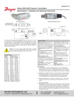
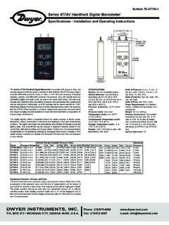
1 F-V7:V-13 2/10/10 3:42 PM Page 1. Bulletin F-V7. Series V7 Vane Operated Flow Switch . Specifications - Installation and Operating Instructions NORMALLY CLOSED. NORMALLY OPEN. 1 NPT COMMON GROUND. 11/16 1-3/8. [ ] [ ] Pipe Size DIM A. 1/2 FEMALE 1 1-17/64 [ ]. 3/4 .554. NPSM. [ ] 1-1/4 1-19/32 [ ]. A 6-31/32 [ ] 1-1/2 1-53/64 [ ]. 2 2-11/64 [ ]. 3 2-11/64 [ ]. 4 2-11/64 [ ]. 2-37/64. [ ]. 2X 47/64. [ ]. The Series V7 Flotect Flow Switch is an inexpensive Switch for use with com- SPECIFICATIONS. patible liquids to start or stop electronic Operated equipment when flow or no-flow Service: Liquids compatible with wetted materials that are non-coating and non- conditions occur. Magnetic operation is simple and dependable with no mechanical crystallizing. linkages or seals to wear or leak.
2 Lower body is machined solid metal bar stock as- Wetted Materials: Vane: 301 SS, Process Connection: brass or 316 SS, Magnet: suring no leak points, no matter how long the unit is in service. Design is standard ceramic, Other: 301, 302 SS. weatherproof, meeting NEMA 4X, for application versatility. Robust vane design is Upper Body Material: Die cast aluminum. rigid and field trimmable for set point adjustment. Process Temperature Limits: -40 to 250 F (-40 to 121 C). Maximum Ambient Temperature: 181 F (83 C). Pressure Limits: 250 psi ( bar). Enclosure Rating: Weatherproof, meets NEMA 4X (IP66). Example V7 W B S 3 0 N ST V7-WBS-30N-ST. Switch Type: SPDT snap Switch . Series V7 V7 Flow Switch Electrical Rating: 10A @ 125, 250, 480 VAC; 1/8 hp @ 125 VAC, 1/4 hp @ 250. Construction W Weatherproof VAC.
3 Lower Body B Brass Electrical Connections: 3 screw type, common, normally open and normally S 316 SS. closed. Circuit Type S SPDT. Conduit Connection: 1/2 NPSM. Connection 3 1 . Process Connection: 1 male NPT. Contact factory for optional tees. Size Pipe Size: 1 to 4 inch. Vane Size 0 Full length vane Mounting Orientation: Horizontal or vertical (actuation flow rates are based on with template horizontal pipe runs in the vertical position). Will not work in vertical pipe with down Tee & Tee N No Tee flow. Material Set Point Adjustment: Vane is trimmable, see set point chart. Options ST SS tag Weight: 1 lb 2 oz (500 g). RV Reinforced vane Approvals: UL353. OPERATING PRINCIPLE. The flow Switch is installed in a pipe to indicate flow/no-flow status. The paddle or vane moves against a spring mechanism in the direction of flow with respect to the amount of flow in the pipe.
4 A magnet is located on the end of the vane inside the lower housing. A second magnet located inside the upper housing moves from magnetic attraction with the magnet attached to the vane. This upper magnet is attached to a lever arm that activates a snap Switch . The upper housing and lower housing are separated by solid metal with no linkages or mechanisms to fail or wear creating leaks. The spring mechanism returns the vane to the original position as flow decreases. ANDERSON DIV., Dwyer Phone: 219/879-8000 Instruments , INC. Fax: 219/872-9057 e-mail: BOX 358 MICHIGAN CITY, INDIANA 46361 F-V7:V-13 2/10/10 3:42 PM Page 2. INSTALLATION Mounting Unpacking Location Remove the V7 from the shipping carton and remove any packaging material. The process pressure and temperature, and ambient temperature must be Inspect for damage.
5 If damage is found, notify the carrier immediately. within specified limits. Make sure the cover is easily accessible to allow for wiring. Set Point The Switch can be installed in any position but the actuation/deactuation flow rates Install unit into piping with 1 NPT bushing with housing cover facing perpendicular are based on horizontal pipe runs and are nominal values. The V7 enables the to flow, see Figure 2 below. When bushings are used they must be back drilled to installer to choose the approximate actuation/deactuation flow rates by trimming allow proper clearance. Bore the to 1 (25 mm). The depth of the bore must the full size vane according to the template on the vane as shown in Figure 1. leave internal threads 9/16 (14 mm) high for proper engagement between lower flows in the following chart are based on installation in standard tees, except the housing of the Switch and the bushing.
6 When threading into pipe use wrench on four inch which is in a 4 x 1 pipe saddle. flats on lower housing only. Check proper vane travel and Switch operation after mounting. Approximate Actuation-Deactuation Flow Rates for Cold Water Actuate GPM [lpm]/Deactuate GPM [lpm]. Vane 1 NPT 1-1/4 NPT 1-1/2 NPT 2 NPT 3 NPT 4 NPT Switch MUST. a (full [ ]/ [ ]/ 58 [218]/ BE MOUNTED. PERPENDICULAR WRENCH ON FLATS. vane) [ ] [112] 52 [197 TO THE FLOW. b [ ]/ [ ]/ FLOW. [ ] 12 [ ]. c [ ]/ 14 [53]/. [ ] [ ]. d [ ]/ [ ]/. [ ] [ ]. e [ ]/ [64]/. [ ] [ ]. FIGURE 2. f [ ]/ [ ]/. [ ] [ ]. g ELECTRICAL CONNECTIONS. Installation must be made in accordance with local codes and h regulations. Wire according to Switch action required. The (normally open) contacts will close and (normally closed).]
7 I contacts will open when flow increases to the actuation point. The contacts will return to normal condition when flow decreases to j [ ]/ the deactuation point. [ ]. k The conduit connection must be made such that condensation is not allowed to enter the Switch housing. If necessary install a conduit breather in a separate l conduit body to prevent buildup of moisture. If nonmetallic conduit is used the protective ground may be connected to the internal ground connection screw. Use m 90 C copper conductors only. n NORMALLY CLOSED. o NORMALLY OPEN. COMMON GROUND. NORMALLY. NORMALLY. COMMON. CLOSED. OPEN. FIGURE 3. MAINTENANCE & REPAIR. 1-7/8 Inspect and clean wetted parts at regular intervals. The cover should be in place at [ ] all times to protect the internal components from dust, dirt and weather.
8 Disassembly or modifications made by the user will void the warranty and could impair the continued safety of the product. If repair is required obtain a Return Goods Authorization (RGA) number and send the unit, freight prepaid, to the address below. Please indicate a detailed description of the problem and conditions under which the problem was encountered. 5/8. [ ] Dwyer Instruments , Inc. Attn: Repair Department FIGURE 1. 102 Indiana Highway 212. Michigan City, IN 46360. Copyright 2010 Dwyer Instruments , Inc. Printed in 2/10 FR# 82-443693-00 Rev. 3. ANDERSON DIV., Dwyer Phone: 219/879-8000 Instruments , INC. Fax: 219/872-9057 e-mail: BOX 358 MICHIGAN CITY, INDIANA 46361