Transcription of Seriously Pro
1 Seriously Pro Racing F3 Flight Controller Thank you for directly supporting the Cleanflight project with your purchase. Seriously Pro Racing F3 Flight Controller Manual (Revision 4). Copyright 2015 Dominic Clifton About The Seriously Pro Racing F3 Flight Controller ( spracingf3 ) was designed to give awesome flight performance based on tried and tested sensors whilst also providing unparalleled I/O capabilities in a small and extremely lightweight form-factor using a next-generation CPU. The spracingf3 gives you all the features you need for the heart of your aircraft, whether you're into FPV racing, acrobatic flying or aerial photography it's perfect. Features No compromise I/O. Use all the features all the time; Connect your OSD + SmartPort + SBus + GPS + LED. Strip + Battery Monitoring + Sonar + 8 motors - all at the same time! On-board high-capacity black box flight log recorder - optimize your tuning and see the results of your setup with- out guesswork (Acro and Deluxe).
2 Next-generation STM32 F3 processor with hardware floating point unit for efficient flight calculations and faster ARM-Cortex M4 core. Stackable design - perfect for integrating with OSDs and power distribution boards. 16 PWM I/O lines for ESCs, Servos and legacy receivers. 8 available on standard pin headers. 8 via side mounted connectors. Full support for OneShot ESCs for easy PID tuning and a sharper response. Supports SBus, SumH, SumD, Spektrum1024/2048, XBus, PPM, PWM receivers. No external inverters required (built-in). Dedicated output for programmable LEDs - great for orientation, racing and night flying. Dedicated I2C port for connection of OLED display without needing flight battery. Battery monitoring ports for voltage and current. Sonar support for precision low-altitude hold. Buzzer port for audible warnings and notifications. Developer friendly debugging port (SWD) and boot mode selection, unbrickable bootloader.
3 Symmetrical design for a super tidy wiring. Wire up using pin headers, JST-SH sockets or solder pads. Use either right-angled or straight pin-headers. Barometer mounted on the bottom of the board for easy wind isolation. Loop times up to ~2x as fast as previous-generation STM32F1 based boards. Configuration of the flight controller via a cross-platform GUI (Windows/OSX/Linux). Supports a variety of aircraft, tricopters, quadcopters, hexacopters, octocopters, planes and more. Available in Acro and Deluxe versions. Variations Acro: Standard model for racing/acro flying. Deluxe: Additional sensors for altitude and direction. Software The spracingf3 runs the open-source Cleanflight flight control (FC) software which has an ever-growing communi- ty of friendly developers and users. Being open-source means that you too can contribute to the system. Cleanflight comes with a detailed manual that is reviewed and maintained by the Cleanflight developers and community.
4 No more out-of-date wiki pages and second-hand information. See for links to the manual. PDF copies can be downloaded from the github releases pag- es. Ensure you reference the manual that is appropriate to your firmware version. History The hardware was designed by the lead developer of Cleanflight, Dominic Clifton, to be more capable than the STM32F1-based boards after hearing feedback from the Cleanflight users, contributors and top-pilots. spracingf3 - Page 2. WARNINGS. Failure to adhere to these warnings will void your warranty and destroy your flight controller. Observe polarity at ALL TIMES. Check and DOUBLE CHECK before applying pow- er. POWER OFF before unplugging, plugging in or making any connections. Connect only one SOURCE of power to the VCC pins / Do not connect more than one source of power to two or more of the VCC pins. If you are using ESCs with BECs then remove the center RED wire from all but one ESC connector.
5 Do not connect GND, VCC or to each other (short circuit). Do not connect GND, VCC or to any inputs or outputs unless specifically stat- ed. Do not connect any input or output to any other input or output unless specifically stated. The supply is for low-current use only. 100mA MAX. Do not allow dirt/dust/glue/etc into the pressure sensor (barometer). Keep magnets away from the flight controller. Do not use a voltage source higher than Check your 5v suppy is actually outputting volts, check it before powering the FC - do not just assume it is 5v. Do not connect a LiPo to the VCC pins. GENERAL ADVICE. Follow the advice below for best performance and long-life of your flight controller: Apply resin/glue to reinforce JST-SH connectors - helps if you crash your aircraft. To further protect the board from crashes you can add a some additional solder to the edges of the JST-SH and USB sockets to reinforce them. Using an enclosure/box for the flight-controller is recommended.
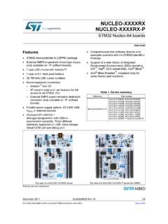
6 Install open-cell foam under the pressure sensor - sandwich some between the FC. and frame. Route motor/battery wires as far away from the compass sensor (magnetometer). as possible. Only install the BOOT jumper pins if you need them. Using color coded pin headers is recommended (not supplied), especially for VBAT. headers. Do everything you can to prevent vibrations reaching the accelerometer/gyro sen- sor. balance props, motors and secure everything. spracingf3 - Page 3. 1. TOP 2. 1. SWD Debugging A. Power LED. connector B. Status LED. 2. UART2 connector C. Orientation indicator 3. Micro USB socket A B D. Accelerometer & Gyro 4. UART3 headers 3 sensor 5. UART1 headers E. Magnetometer (Compass 6. IO_1 connector 4 5 sensor, Deluxe Only). 7. IO_2 connector C F. 8Mb Flash Storage 8. Battery voltage E G. STM32F303 processor monitoring headers 6 D 7 with FPU. 9. Buzzer headers H. M3 mounting hole 10. ESC / Servo output headers G.
7 11. Boot headers 8 9. F. 1 2. 3. UART2 (2). Table Legend 1. Port name H. 2. Port number 1 l GND. 3. PCB marker / Pad 2 VCC. shape 10. 3 TXD/SWDCLK. 4. Pin number 11. 4 RXD. 5. Cable color 4 6. Signal Name 7. Signal Color 5 6 7. SWD/DEBUG (1) UART2 (2) SWD/DEBUG connector - Used for software development or flashing via SWD. 1 l GND 1 l GND Cannot be used when UART2 is enabled. Use an ST-Link debugger with OpenOCD or a J-Link debugger. 2 NRST 2 VCC. 3 SWDIO 3 TXD/SWDCLK UART2 connector - Used for Serial IO. (GPS, etc.). 4 SWDCLK 4 RXD MUST NOT be used when SWD port is in use. UART3 (4) UART1 (5) UART3 headers - Used for Serial IO. (Serial RX, etc.). 1 n GND 1 n GND MUST NOT be used when PWM RX is in use. MUST NOT be used at the same time as IO_2 CH3/4. 2 l VCC 2 l VCC. 3 l TXD 3 l TXD UART1 headers - Used for Serial IO. (OSD, etc.). 4 l RXD 4 l RXD. MUST NOT be used when a cable is connected to the USB port. IO_1 (6) IO_1 connector - PWM RX / PPM RX / GPIO / LED Strip 11 GND When using a PWM receiver connect CH1/2/5/6 to PWM RX.
8 2 VCC. 3 CH1 / PPM LED Strip data signal can be used to change individual colors of each LEDs on a strip of WS2812 RGB leds - 4 CH2 / GPIO Perfect for battery warning lights, orientation lights, indicators, failsafe, display flight modes, etc. 5 CH5 / GPIO CH1/2/5/6 can be used as a general purpose IOs when not used for PPM/PWM RX. 6 CH6 / GPIO. 7 LED_STRIP A output is also available. 8 8 IO_2 (7) IO_2 connector - Serial RX / PWM RX / GPIO / UART3. 11 GND When using a PWM receiver connect CH3/4/7/8 to PWM RX. 2 VCC. 3 CH3 / RXD When using a Serial RX receiver ( , SUMD/H, etc.) use GND/VCC/CH3 (UART3 RX). 4 CH4 / TXD CH3/4/7/8 can be used as general purpose IO when not used for Serial/PWM RX. 5 CH7 / SONAR TRIGGER. 6 CH8 / SONAR ECHO CH7/8 can be used for a Sonar sensor when not used for PWM RX. 7 ADC_1 / CURRENT METER. ADC_1/2 can be used to connect Battery Current Monitoring and RSSI signals. ( MAX). 8 8 ADC_2 / RSSI.
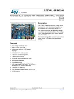
9 VBAT (8) VBAT headers - Connect flight battery for voltage monitoring, logging and warnings 1 n GND / BATTERY NEGATIVE - WARNING: DOUBLE CHECK POLARITY! 2 l BATTERY POSITIVE +. BUZZER (9) Buzzer headers - Connect to a buzzer for warnings and notifications 1 n BUZZER - Use a low-power ~50mA buzzer that only requires power to produce sound, Sonicrest HCM1205X. 2 l VCC / BUZZER + See Cleanflight manual for links. Can also be used to find your aircraft after a crash. OUTPUTS 1 - 8 (10) OUTPUT headers - Connect up to 8 motors and/or servos 1- Currently supports PWM ESCs (400hz default), Oneshot 125 ESCs and PWM servos (50hz default). 2 + VCC. 3 S SIGNAL WARNING: Configure outputs before connecting power to servos and ESCs. BOOT (11) Boot Headers - Used for recovering firmware 1 l No connection = Boot Normally 2 l BOOT Bridged = STM32 Bootloader spracingf3 - Page 4. 1. BOTTOM 2. 1. UART1 connector A. Barometer (Pressure sensor, 2.)
10 I2C1 connector Deluxe Only). 3. ADC pads (Current, RSSI). 3 4. 4. PPM & GPIO pads 5. SONAR pads 6. LED_STRIP & pads A. 5 6. UART1 (1) UART1 headers - Used for Serial IO. (OSD, etc.). 1 l GND MUST NOT be used when a cable is connected to the USB port. 2 VCC. MUST NOT be used at the same time as the UART1 headers. 3 TXD. 4 RXD. I2C1 (2) I2C1 connector - Used for external sensors and OLED displays. 1 l GND The SCL and SDA are signals. 2 3 SCL. is always supplied via the on-board voltage regulators, even when powering via USB. 4 SDA WARNING: logic level converters are REQUIRED if your sensors require signals. SOLDER PADS (3) Solder pads n CH1 / PPM Use instead of the JST-SH connectors as-required. n CH2 / GPIO. n ADC1 / RSSI NOTE: Good soldering skills required. n ADC2 / CURRENT METER. n CH7 / SONAR TRIGGER. n CH8 / SONAR ECHO. n LED_STRIP. n Soldering IMPORTANT: Use a high quality soldering iron and good solder. Tin/Lead solder is MUCH easier to use other Lead-free solder.