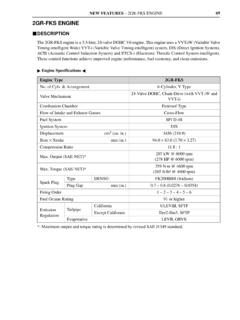
Transcription of SERVICE BULLETIN - McKenzie Tank Lines
1 SERVICE BULLETIN . NUMBER: SB-213-032. DATE: 4/1/04. MODEL: ASET , E-Tech . (Also applies to Mack Trucks Australia). (Supersedes BULLETIN SB-213-032 dated 3/1/02). VALVE LIFTER, CAMSHAFT AND OTHER VALVE TRAIN CHANGES. ASET AND E-TECH ENGINES. Beginning January 16, 2002, (engine serial No. 1Y2008), several changes were made to the valve lifters, camshaft, pushrods and upper valve train components for ASET and E-Tech . engines. These changes, along with revisions to the valve adjustment procedures brought about by the new-style pushrods, are described in this BULLETIN . Valve Lifters The roller lifter has been totally redesigned, with two longer lands that provide more bearing area than the previous design, and the lifter body is now made of hardened steel for greater scuff resistance.
2 The bronze axle used in the previous design has been replaced with a steel axle having a smaller diameter for optimization of roller and axle sizes. The pressure oil feed hole to the axle has been eliminated and replaced with oil grooves on the inside of the lifter legs. The lifter roller is composed of a ceramic material specifically designed for use in engine components. The part number for the ceramic roller lifter assembly is 72GC372. 1. Figure 1 Ceramic Roller Lifter Assembly SB-213-032 Page 1 of 19. SERVICE PUBLICATIONS, ALLENTOWN, PA 18105 MACK TRUCKS, INC. 2002. REV A steel roller variation of the ceramic roller lifter was developed and implemented into a limited production run of 1,100 engines manufactured during July through September 2002 (engine serial No.)
3 Series 2N through 2R). These steel roller lifter equipped engines were installed in certain CV, RD, DM, MR and LE model chassis that were manufactured during the same July through September time frame. Any CV, RD, DM, MR or LE. model chassis equipped with an E-Tech CCRS engine having a serial number beginning with 2N, 2O or 2R should be considered as having the new steel roller lifters. Any MR chassis having an ASET engine with a serial No. series 2N, 2O or 2R. may have steel roller lifters. The new steel roller lifters (part No. 72GC373A) incorporate all the improvements that were developed for the ceramic roller lifter body, and are different only by having a bronze axle and steel roller.
4 This group of engines equipped with the steel roller lifters retained the spring-loaded pushrods and the associated hardware changes that were incorporated with the ceramic roller lifters. REV Ceramic Roller Lifters and Impact Damage Ceramic roller lifters have been used in heavy-duty diesel engines for a number of years, and have provided excellent durability. They are particularly tolerant of roller skidding which is inherent to roller lifter applications. Ceramic rollers, however, will not tolerate high impact loads. Such loads can crack the ceramic, resulting in breakage or spalling of the roller.
5 It is extremely important that a ceramic roller which has been subjected to high impact not be used. Some typical causes of impact damage are as follows: Mishandling or dropping the roller lifter prior to, or during assembly. Do not use a lifter that has been dropped or mishandled. Ceramic roller lifters require the use of spring-loaded pushrods at the exhaust locations. DO NOT use standard pushrods at the exhaust locations. The exhaust lobes of camshafts used in domestic engines have a base circle and a sub-base circle, a design sometimes referred to as a brake-bump. If standard pushrods are used with this type or exhaust lobe design, the brake bump will transmit impact loads to the ceramic roller, resulting in roller breakage.
6 A pushrod that is not properly installed into the lifter cup as the rocker shaft is being installed, and subsequently snaps into the cup when the engine is rotated will break or damage the roller. Replace any ceramic roller lifter that has been subjected to such an impact load. When installing a camshaft, or performing any other type of SERVICE or repair in which removal/reinstallation of the rocker shaft assembly was necessary, failure to have the rocker adjusting screws completely retracted into the rocker arm adjusting screw bore at reassembly can cause breakage of the ceramic rollers. If even one screw is SB-213-032 Page 2 of 19.
7 Extended too far, and either the rocker shaft mounting bolts are tightened or the engine is rotated for valve lash adjustment , immense pressure can be generated against the lifter roller. Even when using just the engine barring tool to rotate the engine, extreme loads can be generated for only a small resistance in turning the engine. This improper assembly can cause a crack or a complete failure of the ceramic roller, a slightly bent pushrod or slightly bent valve. In some cases, the ceramic roller, pushrod or valve will fail later in SERVICE due to the damage caused by improper assembly during cam installation or valve train SERVICE .
8 If engine lock-up occurs when rotating the engine to adjust valves , first determine the cylinder where the valves were starting to open and valve-to-piston contact has resulted in engine lock-up. After determining the affected cylinder, determine and correct the root cause. Additionally, with the rocker shaft assembly and the nozzles removed, apply shop air pressure to the affected cylinder through the nozzle hole. If there is air leakage past the affected valve, the valve has been bent and must be replaced. In all cases, the pushrod and the ceramic roller lifter affected by the engine lock-up MUST be replaced.
9 A lifter that does not move freely in the lifter bore can be impacted by the cam lobe during engine operation. This will result in damage or breakage of the ceramic roller. During lifter installation, always ensure free movement of the lifter in the lifter bore. If the lifter does not move free in the bore, try installing it into another bore. If it moves freely in another bore, it is OK to use the lifter. If the lifter does not move freely when tried in another bore, do not use the lifter. When installing an H-ring, it is possible for Loctite to run down the lifter bore. The Loctite will not cure until the lifter is installed, because the tight clearance between the lifter and bore produces the environment in which the Loctite can cure.
10 If a lifter is adhering to the lifter bore because of dried Loctite , it may snap into place when the rocker shaft assembly is installed, or when the engine is rotated. It may also be possible that the lifter is far enough down the bore that it will not snap into place. In any event, the lifter will not have free movement in the lifter bore if it is contaminated with dried Loctite . The result of either of these conditions (snap into place or adhered to the bore), is possible impact damage to the ceramic roller. To prevent this from occurring, use a suitable solvent to clean any excess Loctite from the lifter bore immediately after installing the H-ring.