Transcription of Servoproportional directional valves in sleeve …
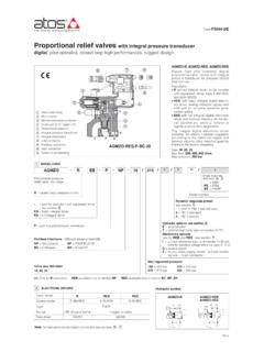
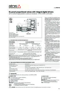
1 Servoproportional directional valves in sleeve executiondigital,direct operated, with position transducer and zero spool overlap with fail safeDLKZOR-TES-SN-BC-160(1) Only for configuration 40(2) In standard configuration the solenoid with integral electronics and position transducer are at side port B(3) Only for TEB and TES-SN. Double power supply only for TESI ntegral electronicsUSB connectorFieldbus connectorMain connector Valve bodySpoolSleeveProportional solenoidPosition transducer FS180 SeriesnumberDLHZODLHZO= size 06 DLKZOR = size 10-/--1 MODEL CODES eals material, see sections, :- =NBR PE= FKM BT = HNBR89 Configuration:40=60=Option/BStandard040L 73**/*--TESNPSN1 = 3 = Valve sizeISO 4401:0 = 061 = 10 Alternated P/Q controls,see section :SN = noneSP = pressure control (1 pressure tranducer)SF = force control (2 pressure tranducers)SL = force control (1 load cell)5 Integral digital drivers, closed-loopone LVDT transducer:TEB = basic, only in version SN-NPTES = fullwith fail safe configuration 1 or 3without fail safeFail safe configuration - see section.
2 13 ABFieldbus interfaces,USB port always present:NP = Not present BC = CANopen EH = EtherCATBP = PROFIBUS DP EI = EtherNet/IPEW= POWERLINK EP = PROFINET IRTS pool type- regulating characteristics:L =linearT =not linear(1) V = progressive D = differential-linear (1) P-A = Q, B-T = Q/2 P-B = Q/2, A-T = Q DT = differential-not linear (1) P-A = Q, B-T = Q/2 P-B = Q/2, A-T = QSpool size: 0 (L) 1 (L) 1 (V) 3 (L) 3 (V) 5 (L,T) 7 (L,T,V,D,DT)DLHZO = 4 7 8 14 20 28 40 DLKZOR = - - - 60 - - 100 Nominal flow (l/min) at p 70bar P-TNote:select 1for configuration 60even without fail safeHydraulic options, see section:B = solenoid, integral electronics and position transducer at side of port A (2)Y = external drainElectronic options,see section:Note.
3 F, Q, Z options are standard for SP, SF, SLC = current feedback for pressure transducer 4 20mA(omit for std voltage 10 VDC) only TES-SP, SF, SLF= fault signal - only TEB andTES-SNI = current reference input and monitor 4 20mA(omit for standard 10 VDC)Q = enable signal - only TEB andTES-SNZ= double power supply, enable, fault and monitorsignals - 12 pin connector (3)1415 Table FS180-3/EDLHZO-TEB, DLHZO-TES DLKZOR-TEB, DLKZOR-TES Digital Servoproportional valves , directoperated in sleeve execution with positiontransducer and zero spool overlap for bestperformances in any position closed integral digital electronic driver performsthe valve s hydraulic regulation according tothe reference signal and assures valve-to-valve interchangeability thanks to the execution with analog referencesignal and USB port for software functionalparameters execution which includes alsooptional alternated P/Q controls and fieldbusinterfaces for functional parameters setting.
4 Reference signals and real-time TEZ (see tech. table FS230) versionintegrates closed loop axis control functions,while TEB and TES versions can be used incombination with remote Z-BM-KZ digital axiscontroller (see tech. table GS340).Size: 06and 10 Max flow: 70and 160 l/min Max pressure: 350 and315 barSafety optionTUV certified - only TES:U= safe double power supply See sectionand tech table FY10072 GENERAL NOTESAtos digital proportionals valves are CE marked according to the applicable directives ( Immunity and Emission EMC Directive).Installation, wirings and start-up procedures must be performed according to the general prescriptions shown in tech table F003and in theuser manuals included in the E-SW-* programming P/Q CONTROLS- only for TES, see tech.
5 Table GS002S*options add the closed loop control of pressure (SP) or force (SFand SL) to the basic functions of proportional directional valves flow regu-lation. A dedicated algorithm alternates pressure (force) depending on the actual hydraulic system conditions. An additional connector is available for transducers to be interfaced to the valve s driver (1 pressure transducer for SP, 2 pressure transducersfor SF or 1 load cell for SL). The alternated pressure control (SP) is possible only for specific installation 12 pin connector is the same as /Z option plus two analog signals specific for the pressure (force) allows valve direct communication with machine control unit for digital reference, valve diagnostics and settings.
6 These executionallow to operate the valves through fieldbus or analog signals available on the main connector. 4 FIELDBUS - only for TES, see tech. table GS510 Digital Servoproportional with integral electronics TEZinclude valve s driver plus axis controller, performing position closed loop of any hydrau-lic actuator equipped with analog, encoder or SSI position transducer. S* option add alternated P/Q control to the basic position ones. Atos also supplies complete servoactuators integrating servocylinder, digital Servoproportional valve and axis controller, fully assembled andtested. For more information consult Atos Technical CONTROLLER- see tech. table FS2307 SAFETY OPTION- only for TES, see tech. table FY100 Atos range of proportional directional valves , provides functional safety option /U, designed to accomplish a safety function, intended to reduce the risk in process control SETTINGS AND PROGRAMMING TOOLS- see tech.
7 Table GS001 The main setting of valve s functional parameters and configurations are:- bias, scale, ramps, dither- linearization function for the hydraulic regulation- setting of PID gains- selection of analog IN / OUT range- complete diagnostics of driver status- internal oscilloscope function- in field firmware update through USB port8 SEALS AND HYDRAULIC FLUID - for other fluids not included in below table, consult Atos Technical OfficeSeals, recommended fluid temperature NBR seals (standard) = -20 C +60 C, with HFC hydraulic fluids = -20 C +50 C FKM seals (/PE option) = -20 C +80 C HNBR seals (/BT option) = -40 C +60 C, with HFC hydraulic fluids = -40 C +50 C Recommended viscosity20 100 mm2/s - max allowed range 15 380 mm2/sFluid contamination classISO 4406 class 20/18/15 NAS 1638 class 9, in line filters of 10 m ( 10 _>75 recommended)Hydraulic fluidSuitable seals typeClassificationRef.
8 StandardMineral oilsNBR, FKM, HNBRHL, HLP, HLPD, HVLP, HVLPDDIN 51524 Flame resistant without waterFKMHFDU, HFDRISO 12922 Flame resistant with waterNBR, HNBRHFCV alve's functional parameters and configurations, can be easily set and optimized using Atos E-SW programming software connected via USBport to the digital driver. For fieldbus versions, the software permits valve's parameterization through USB port also if the driver is connected tothe central machine unit via connectionTESTEBE-C-SB-USB/M12 cableE-A-SB-USB/OPT isolatorThe software is available in different versions according to the driver s options:E-SW-BASIC support: NP (USB) PS (Serial) IR (Infrared)E-SW-FIELDBUS support: BC (CANopen) BP (PROFIBUS DP) EH (EtherCAT) EW (POWERLINK) EI (EtherNet/IP) EP (PROFINET IRT)E-SW-*/PQ support.
9 valves with SP, SF, SL alternated control ( E-SW-BASIC/PQ)It is TUV certified in compliance toIEC 61508 up to SIL 3 and ISO 13849 up to category 4, PL eSafe double power supply, option/U: the driver has separate power supplies for logic and solenoidsWARNING: drivers USB port is not isolated!The use of isolator adapter is highly recommended for PC protection (see table GS500)Notes: (1)For different p, the max flow is in accordance to the diagrams in section (2)Referred to spool in neutral position and 50 C oil temperature (3)0-100% step signal9 GENERAL CHARACTERISTICSV alve modelDLHZO-TEB, TESDLKZOR-TEB, TESP ressure limits [bar]ports P, A, B = 350; T = 210 (250 with external drain /Y)ports P, A, B = 315.
10 T = 210(250 with external drain /Y)Spool typeL0L1V1L3V3L5T5L7T7V7D7DT7L3L7T7V7D7D T7 Max flow (1) [l/min]at p = 30 bar p P-T at p = 70 barmax permissible flow2,54,58913182626 13406060 3347121420284040 2060100100 50814163040507070 4090160160 80 Leakage [cm3/min] at P = 100 bar (2)<100<200<100<300<150<500<200<900<200< 200<700<200<1000<1500<400<400<1200<400 Response time (3) [ms] 10 15 Hysteresis [% of max regulation] 0,1 0,1 Repeatibility [% of max regulation] 0,1 0,1 Thermal driftzero point displacement < 1% at T = 40 CFS18011 ELECTRIC CHARACTERISTICSNote:a minimum booting time between 400 and 800 ms has be considered from the driver energizing with the 24 VDCpower supply beforethe valve has been ready to operate.