Transcription of SET POINT TESTING An investigation of safety relief valve ...
1 SET POINT TESTING An investigation of safety relief valve set POINT TESTING techniques By E. Smith - BP Amoco Exploration, Sunbury, England, and J. McAleese - City University, London, England Introduction In 1995/6 a BP group-wide work group met to consider various aspects of safety relief valve management and performance. One subject considered was the setting of these valves and, in particular, the use of on line set POINT verification (OLSPV). Traditional methods of TESTING such valves in BP Amoco group companies conform to the recognised industry standard API 576, and the usual procedure requires that all PSVs are removed from the plant periodically so that their condition can be evaluated in a workshop. Prior tore-installation valves are then "pop" tested on a test bench. On steam boilers the bench set pressure must also be proven in-situ by "floating" the valve . This method is both time consuming and costly. There are, however, methods of TESTING safety relief valves on line (with and without pressure), notably the Furmanite 'Trevitest" safety valve TESTING system and comparable in-situ test systems offered by Crosby and Consolidated.
2 The benefits of these methods are lower costs and, where valves are not "spared", extended plant run times. Although these techniques are well established in the power generation industry on steam service confidence in process industries has been low and little controlled TESTING has been conducted. The Working Group proposed an investigation , carried out in collaboration with the vendors, to test the reliability of OLSPV and better define its limitations. This paper describes the resulting tests. At the same time the opportunity was taken to investigate the accuracy of the widely used bench TESTING technique. Most of the in-situ tests were performed using Furmanite's "Trevitest" system but a smaller number of tests (three valves on air and steam) were also carried out using Tyco Flow Control's Crosby system to provide confirmation of results and a comparison of the techniques. For the two participating vendors (Furmanite and Crosby) the apparatus, hardware and basic operating procedure were similar, differing mainly in the software and presentation of data.
3 Other vendors may offer different in-situ test methods. (The inclusion of these two vendors in the programme does not imply approval and is not a comment on competing techniques which were not evaluated.) Note that, regardless of the method of set POINT verification employed, it is necessary to remove relief valves periodically in order to inspect and refurbish the valve internal parts and to inspect and maintain pipework. The necessity is greater on dirty, fouling or corrosive duties than on clean service. Description of the on-line set POINT verification technique A hydraulic power pack supplies energy to a hydraulic ram located in the cross-head of a mechanical rig. The hydraulic ram displaces vertically upwards, overcoming the spring force and causing the valve to lift when the upward force exerted by the working fluid overcomes the downward force exerted by the spring. The force generated during this operation is measured using a strain gauged load cell and recorded on a portable computer where it can be converted into an equivalent pressure.
4 If the test is undertaken with line pressure present, the calculated pressure is added to the line pressure present to give the as-found set pressure. Line pressure is measured by means of a calibrated pressure transducer connected to the portable computer. valve lift is measured and recorded using a displacement transducer. The computation of this information, captured graphically on portable computer, leads to the determination of the set pressure, valve lift or displacement, spring adjustment rate, an indication of the effect of the nozzle and guide rings and the re-seat pressure. The accuracy with which the effective seat area of the valve is known has an effect on the accuracy of set pressure prediction. In this case the valve seat area was estimated based on average seat face width. A more accurate approach is to conduct a "fingerprint" test under known conditions which allow the effective seat area to be calculated and recorded for future use. Test objective The aim was to assess the effects of operating pressure, seat area, test fluid, and valve design on the accuracy of OLSPV and to compare actual lift pressure, bench set pressure and on-line set pressure.
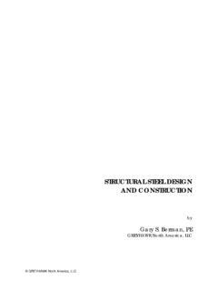
5 Test equipment The test rig is shown in Figure 1. It was constructed to Class 300 rating and consisted of a 6" manifold with flanged nozzles of 1", ", 2" and 3" diameter. Where increased volume was required a length of 6" diameter pipe was connected to the manifold. Test fluids were as follows: Steam from a 200 psi main via a PCV. Air from a main via a PCV Water from a pressurised flow loop via a PCV Oil from an air driven hydro-pump fitted with an accumulator to reduce pressure pulsations. Figure 1 Schematic of the test rig (click image to enlarge): Notes: All vents to be run in 1"BSP galvanised pipe Main vessel to be lagged using 50mm thick matting Operating parameters: Design & disk temperature - barg Design temperature - 20 to 200oC Hydrostatic test temperature - barg at ambient Maximum working relief valve pressure - 200 psig Test procedure On arrival at Sunbury, the relief valves were inspected and set to a requested range of bench set pressures by Strata Technology Ltd, the engineering services contractor on site, in a workshop.
6 Cold set tolerances are bar for bench set pressures of 5 bar or below, and 3% for bench set pressures greater than 5 bar. The method conforms with BP Amoco standard practice. The valves were then transported by cart to the test rig and each valve was lifted in-situ whilst at atmospheric internal pressure (0% of bench set pressure) to determine the lift POINT for this condition. The first test medium was air and tests were repeated for each valve using steam, water and oil. The on-line lift pressure was determined using OLSPV at internal pressures of 30%, 60% and 90% of bench set pressure. The OLSPV apparatus was then removed and the actual lift POINT determined by raising the on-line pressure until the valve popped. Throughout this process the line pressure was monitored using pressure transducers and a chart recorder. Valves tested All valves tested in this investigation were loaned by operating plants. Nine valves were obtained from three different BP Amoco sources.
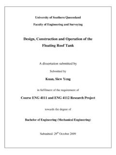
7 All were metal seated and three were bellows sealed. Some were new and some had seen previous service. Details and of each valve are shown in Table 1. Table 1 Details of relief valves tested valve No. Manufacturer valve type Seat ID (mm) OD (mm) Mean seat area (inches2) Bench set pressure (barg) #1 Farris 26JA10-140 36 38 2 #2 Farris 26JA10-140 36 38 3 #3 Bailey Birkett 3K 432 48 17 #4 1F 232 #5 3111 CGB #6 Farris 26DA10-120 15 #7 Crosby JB 25A #8 Broady 2531F-DP XB20 20 #9 Broady 2531F-DP XB20 30 Note: All valves tested had a 'hard seat'. Test results The following is an example of the way in which test results were presented. The specific result is that obtained using the Furmanite Trevitest method on valve No. #9, with an on-line pressure of approximately 30% of the bench set pressure and where the test medium is air. The result first appears in Figure 2. Its position shows that Furmanite's prediction of the actual lift POINT deviates by + from the bench set pressure of valve #9, which is 30 bar; The valve is predicted to lift higher than the bench set pressure and the valve will lift heavy in the event of over-pressure whilst on-line.
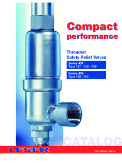
8 The result appears again in Figure 3. This shows the test results accuracy relative to the actual lift POINT for each valve . The plots show that this particular result deviates by from the actual lift pressure for valve #9, which is bar; The OLSPV prediction is conservative, even though, relative to the bench set pressure, the prediction appears un-conservative. Finally the POINT appears in Figure 4. where the percentage deviations of the on-line set POINT verification results from the actual lift POINT for each valve are plotted against the seat size of each valve . valve #9 has a seat size of square inches. The vertical positioning of the result is the same as shown in Figure 3 that is less than the actual lift POINT . Figure 2 Chart showing the percentage deviation of on-line set POINT verification results vs. the bench set pressure for each valve , tested on air (click image to enlarge) Figure 3 Chart showing the percentage deviation of the on-line set POINT verification results vs.
9 The actual lift POINT for each valve , tested on air (click image to enlarge) Figure 4 Chart showing the percentage deviation of the on-line set POINT verification results from the actual lift POINT vs. the seat size of each valve , where the test medium is air (click image to enlarge) Discussion of test results Comparison of the on-line test results with bench set pressure On examination of Figure 2, it is clear that the set POINT verification estimates using either of the on-line test methods are generally higher than the estimates obtained by conventional bench TESTING (bench set pressure). Overall, of the 129 on-line relief valve set POINT verification tests performed on all test media, 88% were greater than the corresponding bench set pressure. Of these 52% were more than 5% greater, and 32% were more than 10% greater than the bench set pressure for each valve . This could imply one of two things; that the on-line relief valve set POINT verification methods err considerably on the side of caution, based on the bench set pressures being reasonably accurate, or conversely that the bench set pressures are un-conservative and relatively inaccurate.
10 (Note: this may not be of practical significance except where operating pressures are close to the set POINT or where equipment with only marginal tolerance of overpressure is employed) Comparison between bench set pressure and actual lift POINT The results comparing the bench set pressure to the actual lift POINT are shown in Figure 5. This shows that, of the 9 valves tested, 8 had actual lift points greater than the bench set POINT for the valve when 'popped' on air, indicating that the bench set valve would lift 'heavy' on-line. Of the 9 bench set pressures 5 deviated by more than +5% from the actual lift POINT , and 3 deviated by more than +10%. Figure 5 Chart showing the deviation of the actual lift POINT vs. the bench set POINT for each valve (click image to enlarge) Comparison of on-line set POINT verification results and the actual lift POINT of each valve The scatter of data shown in Figure 4 shows that the error decreases with increasing valve set pressure. This was as expected.