Transcription of SEWAGE PUMP IMPELLER SELECTION - Pacific Liquid
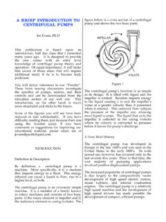
1 SEWAGE PUMP IMPELLER SELECTIONJoe Evans, fundamental difference between a centrifugal SEWAGE pump IMPELLER and those of its clear water cousins is its ability to pass solid material that would normally clog the latter. What differentiates various SEWAGE pump impellers is the method by which they accomplish this. Before we explore these differences, lets review some centrifugal IMPELLER figure below is that of a typical, clear water, Francis vane (radial flow) IMPELLER . Its major parts -- the eye, vane leading edges, and shrouds are labeled. The vane exits can be seen between the shrouds. Figure 1 Although the mathematics that define the operation of an IMPELLER can be complex (it is the stuff of Bernoulli and Euler), its purpose is straight forward. An IMPELLER is designed to impart energy to a fluid so that it will flow or, if it is already flowing, undergo some increase in its elevation or pressure.
2 It accomplishes this by increasing the fluid s velocity as it travels through its vanes from the their leading edges, located at the eye to their exits at the periphery. The ever increasing radius of the vanes results in an increasing rotational velocity that reaches some maximum at the periphery. The resulting linear velocity of the fluid, at the vane exit, is then converted to pressure in the one were to set out to design a typical radial vane IMPELLER , several guidelines would be followed quite closely. For instance, the overall diameter of the IMPELLER would closely match the volute and cut water diameters in order to reduce slippage of the pumped fluid in these areas. Also, depending upon the desired hydraulic characteristics, four or more vanes would be incorporated to smooth flow at the vane exit.
3 And, their leading edges would be sharpened to reduce losses due to friction and turbulence. Unfortunately, if one followed these same guidelines when designing a solids handling IMPELLER , the outcome would be doomed to failure. Unlike the typical radial vane IMPELLER , those designed to accommodate solids violate many of the standard design to medium sized SEWAGE pumps are often referred to as non clogs and their impellers are designed to try to live up to that name. Although many factors contribute to an IMPELLER s ability to pass solids without clogging, one of the more important is its throughlet throughlet is defined as the open internal passage through the IMPELLER that, ultimately, determines the largest diameter solid that can be passed. All impellers regardless of their design have some maximum throughlet size.
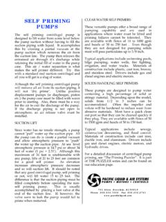
4 In order to maximize throughlet size, solids handling impellers limit the number of vanes so that the passages between them can be as large as possible. Lets take a look at some of the common SEWAGE pump IMPELLER designs and discuss the benefits and limitations of Flow Solids Handling ImpellersThe various members of the radial flow IMPELLER family include the closed, open, and semiopen designs. Depending upon capacity, each design may incorporate from one to four vanes. The vanes are not straight, but describe a smooth curve that begins at the IMPELLER s eye and extends to its periphery. They may also be curved upward at their entry as in the Francis vane design shown in figure 1 The closed IMPELLER , shown below, looks very much like an exaggerated version of the clear water IMPELLER seen in Figure 2 This particular example consists of two vanes with front and back shrouds.
5 The shrouds of the closed IMPELLER enclose the IMPELLER s vane passages from the eye to the periphery and are designed to accommodate the largest possible diameter solids. The vanes themselves have large, rounded leading edges to prevent clogging by rags and stringy material that could become entangled at the vane entry. On pumps with suctions up to 12 , a two vane (often referred to as a two port) design is typical while larger pumps may utilize a three or four vane design. Most closed impellers also incorporate pump out vanes on the back side of the back shroud. These small, straight vanes keep the sealing area free of debris and also reduce the unbalanced axial forces that can occur due to back shroud s larger surface area. The major wearing surface of the closed IMPELLER is the area where the eye protrudes into the volute suction.
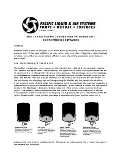
6 Replaceable volute wear rings are used to maintain proper clearance and hydraulic efficiency. A typical rule of thumb calls for wear ring replacement when the factory set tolerance has large SEWAGE pumps often use a mixed flow IMPELLER for low head, high flow conditions. The mixed flow design utilizes a double curvature vane that provides both radial (centrifugal) and axial (lifting) flow characteristics. Also because of their extremely large throughlets (4 and greater) these larger pumps can utilize sharpened vane leading edges for greater efficiency. Another characteristic of the closed solids IMPELLER is that its diameter seldom exceeds 80% of the volute cut water diameter as compared with about 92% for a standard IMPELLER . This diameter is illustrated below and is restricted, at the expense of slippage, in order to reduce vibration and noise especially at lower flows.
7 This larger than normal clearance also reduces clogging in the area where the IMPELLER periphery is closest to the volute WATERDIAMETER Figure 3 Another closed design is the single vane IMPELLER . On the positive side, it allows for the largest possible throughlet and since there is only one vane, there is only one leading edge and thus potential clogging at the vane entry is reduced. Unfortunately, due to its lack of symmetry, it is inherently out of balance. Unlike the multivane IMPELLER , most cannot be trimmed and must be replaced if hydraulic conditions change. The single vane IMPELLER also tends to produce a rather steep head-capacity curve. Although this can be useful in some applications, the flatter multivane curve generally has greater utility.
8 The figure below is that of a semiopen, single vane IMPELLER . In the closed version, the vane is enclosed by a front 4By definition, the true open IMPELLER consists of nothing more than vanes mounted to a hub that is attached to the pump shaft. They are usually seen in smaller pumps and are best suited for applications involving stringy materials. Because they are shroudless, it is less likely for material to become entrapped between the IMPELLER and the front and rear portions of the pump case. A disadvantage is their structural weakness and, because of this, they are often strengthened by a partial shroud on the back side. If the back shroud covers the entire vane structure, the IMPELLER is designated as semiopen. The figure at the top right compares the two one or both shrouds are missing from each design, both are prone to wear at the vane edges and must be adjusted periodically in order to maintain hydraulic 5 Typical volute / vane clearances range from to and increases due to wear affect pump efficiency to a greater degree than does the eye / volute wear of the closed semiopen IMPELLER , due to its lack of a front shroud, also tends to create greater unbalanced axial forces than does the closed IMPELLER .
9 Both pump out vanes and balance holes are often utilized to minimize these forces and prevent potential bearing damage. Although the radial flow IMPELLER is the work horse of the SEWAGE pump industry, there are applications for which it is not well suited. One example is low flow applications. By virtue of its large throughlet, flow rates will always be far greater than impellers of the same diameter designed for clear fluids. For example, even a small IMPELLER designed to pass 2 solids will create BEP (Best Efficiency Point) flows of 80 to 120 GPM. Increase solids size to 3 and the flow range increases to 400 to 700 GPM. With conventional pumps flow can be reduced by throttling the discharge; however, such a tactic is not acceptable when solids are involved. This problem is exacerbated when a low flow application is complicated by a high head requirement.
10 Radial ForcesWhen a centrifugal pump is operating, the pumped fluid exerts a force on its IMPELLER both radially (perpendicular to the shaft) and axially (parallel to the shaft). When the pump is operating at its design point (BEP), relatively uniform pressures act upon most of the IMPELLER s surfaces. An exception is the area about the periphery where pressures are rarely uniform regardless of the operating point. As flow decreases (or increases), unbalanced radial forces increase and usually reach a maximum at or near shut off head. This radial thrust, as it is known, is a function of total head and the width and diameter of the IMPELLER . Thus a high head pump with a large IMPELLER will generate more radial thrust than a low head model incorporating a smaller IMPELLER . By design the SEWAGE pump IMPELLER is unusually wide and the radial forces created can be extremely high as operation moves to either side of BEP.