Transcription of Shear Walls •Load Distribution to Shear Walls
1 Shear Walls1 Load Distribution to Shear Walls Shear wall stiffness Diaphragm types Types of Masonry Shear Walls Maximum Reinforcement Requirements Shear Strength Example: Single Layer Reinforcing Example: Distributed Reinforcing Example: Flanged WallsShear WallsShear Walls2_____ stiffness predominates_____ stiffness predominatesBoth Shear and bending stiffness are importantdhh/d < < h/d < > Force Resisting SystemCantilever Shear WallShear Deflection calculations shall be based on cracked section properties. Assumed properties shall not exceed half of gross section properties, unless a cracked-section analysis is wall = height of wall = Shear area; (5/6) for a rectangle = = Shear modulus (modulus of rigidity); given as ( ) = 21 , where is Poisson s ratio = thickness of wall = length of wallFixed wall(fixed against rotation at top)Real wall is probably between two cases.
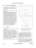
2 Diaphragm provides some rotational restraint, but not full Walls : Stiffness 4 3 3 Shear Walls5 Section Wall intersections designed either to:a) _____: b) _____Connection that transfers Shear : (must be in running bond)a) Fifty percent of masonry units interlockb) Steel connectors at max 4 ) Intersecting bond beams at max 4 ft. Reinforcing of at least foot of wall2-#4 sMetal lath or wire screen to support grout1/4in. x 11/2in. x 28in. with 2in. long 90 deg bends at each end to form U or Z shapeT- or L- Shaped Shear WallsShear Walls6 Effective flange width on either side of web shall be smaller of actual flange width, distance to a movement joint, or: Flange in compression: 6t Flange in tension: Unreinforced masonry: 6t Reinforced masonry: times floor -to- floor wall heightAnalysis: distinction between 6t and times floor -to- floor wall height in compression is not important.
3 Assumed effective width only results in a small shift of neutral people suggest increasing tension flange width by for Shear capacity design and ductility checks. Reinforcement just outside effective width can be Flange Width ( ) Shear Walls7 Rectangular cross-sections T-shaped and I-shaped sections Shear stiffness Partially grouted Walls total cross-sectional area of face shells plus area of grouted cells Cracked Moment of InertiaSeismic Design of Special Reinforced Masonry Shear Walls A Guide for Practicing EngineersNEHRP Seismic Design Technical Brief No. 9 Shear = : Fully grouted Shear wallRequired: Stiffness of wallSolution: Determine stiffness from basic , from outer flangeExample: Flanged Shear WallNet areaNet moment of inertiaShear area.
4 48 ..40 . 671 .. ~ .40 . 305 . 20 86000 . Shear Walls9 Example: Flanged Shear WallUncrackedCracked 1112 3 1800 112 305 1800 111 . 3 1 3 Stiffness 1 112 . 3 1800 86000 . 112 .305 . 1800 .. 283 .Allowable seismic drift: = Walls10_____ Shear wallCoupled Shear WallsSeismic Design of Special Reinforced Masonry Shear Walls A Guide for Practicing EngineersNEHRP Seismic Design Technical Brief No. 9 _____ Shear wall_____ Shear wallShear Walls11 Frame ModelsSeismic Design of Special Reinforced Masonry Shear Walls A Guide for Practicing EngineersNEHRP Seismic Design Technical Brief No.
5 9 Shear Walls12 Frame ModelsSeismic Design of Special Reinforced Masonry Shear Walls A Guide for Practicing EngineersNEHRP Seismic Design Technical Brief No. 9 Shear Walls25 Example: Perforated Shear WallCentral pier carries about 85% of Shear ; can design for entire shearGood practice would be to add control joints10 18 5 3 7 55 3 8 2 8 18 8 3 3 2 1. Need to provide prescriptive seismic reinforcement Need drag strut/collector to get Shear to solid not skimp on end of wall steelControl JointShear Walls261. All elements either need to be isolated, or will participate in carrying the load2. Elements that participate in carrying the load need to be properly detailed for seismic requirements 3.
6 Most Shear Walls will have openings4. Can design only a portion to carry Shear load, but need to ca detail rest of structure5. Can use control joints to isolate piersShear Walls : Building LayoutShear Walls27 Diaphragm: _____ system that transmits _____ forces to the vertical elements of the lateral load resisting system. Diaphragm classification: _____: Distribution of Shear force is based on tributary _____ (wind) or tributary _____ (earthquake) _____: Distribution of Shear force is based on relative Force Resisting SystemTypical classifications:_____: Precast planks without topping, metal deck without concrete, plywood sheathing_____: Cast-in-place concrete, precast concrete with concrete topping, metal deck with concreteDiaphragmsShear Walls28 Direct Shear :Torsional Shear .
7 = total Shear force on building = relative rigidity of lateral force resisting element i = distance from center of stiffness = eccentricity of load from center of stiffnessRigid Diaphragms Total Shear on Wall: Shear Walls29 Given: The structure shown is subjected to a kip/ft horizontal force. Relative stiffness values are : Distribution of force assuming: flexible diaphragm rigid = 4k = 5k = 150 ft50 kip/ftPLAN VIEWE xample: DiaphragmsShear Walls30 Solution: Flexible diaphragm windDistribute based on tributary areaFor seismic, the diaphragm load would be distributed the same (assuming a uniform mass Distribution ), but when wall weights were added in, the forces could be = 4k = 5k = 150 ft50 ftPLAN VIEWE xample: Flexible DiaphragmsShear Walls31 Solution: Rigid diaphragmk = 4k = 5k = 150 ft50 ftWall 1 Wall 2 Wall 3xWallxkx(k)123 TotalCenter of stiffness = 350/10 = 35 ftWallkd (ft)k(d)k(d2) : Rigid DiaphragmsShear Walls33 Solution.
8 Forces are shown for a rigid moment is generally taken through chord forces, which are simply the moment divided by the width of the diaphragm. In masonry structures, the chord forces are often take by bond ft50 kV (k)M (k-ft) ft38-55 Example: Diaphragm Design ForcesShear Walls34 Shear forces: generally considered to be uniformly distributed across the width of the diaphragm. Drag struts and collectors: transfer load from the diaphragm to the lateral force resisting VIEWvvL/2vL/2 WEST WALL ELEVATIONvvLEAST WALL ELEVATIONL/3L/3L/2 Drag Struts and CollectorsShear Walls35 Three lateral force resisting systems: Length=20 ft; Height=14 ftW24x68W14x68 Moment Resisting Frame = Frame = 296 4x4x5/16W16x40 Masonry Shear Wall = 1470 kip/inL 4x4x5/16E = 1800 ksiFace shell beddingEnd cells fully groutedLateral force resisting systems at 24 ft Diaphragm assumed to be concrete slab, = 3120 ksi, = , variable thickness, load of 1 Force Resisting System24 ft24 ftDiaphragm BehaviorShear Walls36 Diaphragm BehaviorShear Walls37 BehaviorShear Walls38 Diaphragm BehaviorShear Walls39_____ (unreinforced) Shear wall ( ): Unreinforced wall_____ (unreinforced) Shear wall ( ): Unreinforced wall with prescriptive 24 reinforcement at 16 in.
9 Or bond beams at 10 not required at openings smaller than 16 in. in either vertical or horizontal direction 16 joint 8 in. 10 ft. 8 and end of wallsWithin 16 in. of top of wallStructurally connected floor and roof levelsReinforcement of at least in2 Shear Walls : TypesShear Walls40_____ reinforced Shear wall ( ): Reinforced wall with prescriptive reinforcement of detailed plain Shear reinforced Shear wall ( ): Reinforced wall with prescriptive reinforcement of detailed plain Shear wall. Spacing of vertical reinforcement reduced to 48 reinforced Shear wall ( ):1. Maximum spacing of vertical and horizontal reinforcement is min{1/3 length of wall, 1/3 height of wall, 48 in.}
10 [24 in. for masonry in other than running bond]}.2. Minimum area of vertical reinforcement is 1/3 area of Shear reinforcement3. Shear reinforcement anchored around vertical reinforcing with standard hook4. Sum of area of vertical and horizontal reinforcement shall be times gross cross-sectional area of wall5. Minimum area of reinforcement in either direction shall be times gross cross-sectional area of wall [ for horizontal reinforcement for masonry in other than running bond]. Shear Walls : TypesShear Walls41 Use specified dimensions, in. for 8 in. CMU Ratio8 in. CMU wall12 in. CMU wallAs( ) Possibilities As( ) #4@32#5@56 #4@24#5@ @24#5@40#6@56 #4@16#5@24#6@ @16#5@ @8#5@16#6@24#7@40 Shear Walls : Special ReinforcedMax spacing 48 Shear Walls42 Example: Reinforcement Spacing56 12 12 8 12 12 9 4 22 9 4 3 4 OpeningOpeningControlJointsIsolated PiersExpected Diagonal Cracks in PiersOpeningOpeningDisplaced shapeIs the reinforcement spacing based on 1/3(3 -4 )?