Transcription of Sheaves and Drums - wwwrope.com
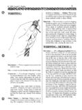
1 Sheaves and DrumsSheaves and Drums play a very important part in overall rope life. To maximize rope service life, it is imperative that the equipment have properly maintained Sheaves and drum and drum DiameterAll wire ropes operating over Sheaves and Drums are subjected to bending stresses, which eventu-ally cause the wire rope to fatigue. The severity of these stresses are directly related to the rope load and the D/d ratio, or the ratio of the tread diameter of the sheave or drum (D) to the diam-eter of the rope (d).In order to bend around a sheave or drum , the rope s strands and wires must move in relation to one another to compensate for the bend. The wires on the top side of the rope elongate while the wires on the underside compress. Simply put, the top side has farther to travel around the sheave then the underside. This continual shifting causes the inner wires to move against one another when the rope is under load. If the sheave or drum is too small, causing a severe bend in the rope, wire movement is adversely affected because the wires cannot easily move to adequately compensate for the bend.
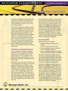
2 Fatigue breaks, high stranding, looped wires, and even-tually failure, will s common knowledge that the larger the sheave or drum diameter, the better the rope s fatigue performance. Practical limits of the equipment s design however may not result in the D/d ratios suggested as shown in Figure 2. If the Sheaves or drum cannot be replaced to provide the proper D/d ratio, other steps such as changing rope construction may be taken to optimize wire rope service SizeDuring normal operations, sheave and drum grooves are under constant pressure. The groove contours must be checked when ropes are changed or end-for-ended. Suggested Construction Minimum D/d Ratio6x26 Warrington Seale 6x25 Filler Wire6x31 Warrington Seale 6x36 Warrington Seale6x43 Filler Wire Seale 6x50 Seale Filler Wire Seale 6x41 Warrington Seale6x41 Seale Filler Wire6x49 Filler Wire Seale 8x25 Filler Wire8x31 Warrington Seale8x36 Warrington Seale6x57 Seale Filler Wire Seale6x64 Seale Filler Wire Seale 6x70 Seale Filler Wire Seale6x77 Seale Filler Wire SealeFigure 2: sheave and drum Ratios100 Maynard St.
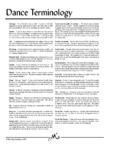
3 Williamsport, PA 17701 USA tel 570-326-5146 fax 570-327-4274 t e c h n i c a l b u l l e t i n 2 Sheaves and DrumsFigure 1: This drawing graphically illus-trates the movement of strands when wire rope is bent over a sheave or drum . Note that the marked area on the outer strands moves as the outer wires elongate and inner wires groove contours as a result of wear can have a dramatic effect on rope life. A tight sheave will cause increased groove pressures at the point of contact. This is indicated when a rope is showing two parallel planes of wear and/or breakage approximately 120 to 150 apart. A rope may eventually become sized to the groove but rope life will right sheave can be determined by using a sheave gauge. To determine if the groove is worn below recommended minimums, use the proper sheave gauge to inspect the groove. Using equip-ment that requires 2-5/8 diameter rope as an example, if the 2-5/8 nominal sheave gauge does not fit completely into a 2-5/8 groove, the groove is worn and will affect the surface wear and fatigue life of the rope.
4 If the next smaller sized gauge (in this cause 2-1/2 ) does not fit either, then a very serious condition exists which greatly affects service life of ropes. In this case the groove should be reconditioned or the sheave / drum lagging types of groove gauges are in general use and it is important to note which of these is be-ing used. The two differ by their respective per-centage over nominal. For new or re-machined grooves, the groove gauge is nominal plus the full oversize percentage, or 5%. The gauge car-ried by most wire rope representatives today is used for worn grooves and is manufactured as nominal plus one-half the full oversize percent-age, or 2-1/2%. This latter gauge is intended to act as a sort of no-go groove that is too large will also have a nega-tive effect on rope performance. An oversized groove does not support the rope and allows it to flatten, thus unbalancing the rope. An unbalanced rope develops internal stresses that exceed design factors and lead to early fatigue of wires, wire breakage and rope crushing.
5 Re-turned rope samples normally show wear to less than 90 on the rope and a possible cast or set to the rope with the wear found to the underside of the cast. These observed conditions confirm that an oversized groove will not provide the support necessary and cause the rope to flatten, lose its integrity and provide a short service best situation is a groove which gives maxi-mum support to the rope. The greater the groove support, the lower the sheave bearing pressures and the longer the rope life. When regrooving a sheave or drum , the recommended contact to rope contour is 150 at no larger than nominal plus 5% and no smaller than nominal plus 2-1/2%.Groove HardnessThe hardness of Sheaves and Drums is often overlooked. Wire rope is a very hard product having a calculated Brinell of 430 to 500 (46RC-51RC). Due to this hardness and the pressures exerted from the rope onto the groove, defects such as groove corrugations occur if the groove is worn through its surface hardness or has not been flame hardened.
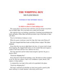
6 Mines typically alternate rope lays to combat corrugations. However, once this condition occurs, the groove needs to be reconditioned and surface hardened. Groove hardness should be in the range of 475 to 540 Brinell (50RC-54RC) to prevent premature wear of the grooves. Correct Tight sheave Loose SheaveFigure 3: Cross sections illustrating three sheave groove conditionsFigure 4: Illustrating the various dimensions of a sheave , and the use of a sheave and Drumst e c h n i c a l b u l l e t i n 2 Groove ProfileOn leaving the sheave , the rope tends to form an angle with the sheave equal to the fleet angle as it rises out of the groove. If the angle of flare ( , angle between the groove flanges) is not great enough, or has a shoulder, the rope will experience accelerated wear. This wear is developed because the rope at-tempts to follow a straight path while a point on the sheave rim or in the sheave groove follows a circular path. A sheave profile as shown in Figure 5 results in the groove undercut shoulder rubbing against the rope.
7 This causes accelerated abrasive wear and potentially the development of martensite (refer to Mining Technical Bulletin 1 for further information) on the outer wires. Any shoulder on the flange caused by deepening of the grooves should be machined off and the minimum angle of flare maintained at all AngleUnder operating loads and speeds, wire rope is subjected to the dynamics of operational forces that are transmitted from the machine to the wire rope. These forces create excessive vibration in the ropes, leading to whipping and/or causing the rope to be in constant contact with other objects, such as deflection Sheaves . To minimize the resultant damage, the fleet angle should be minimized. The schematic in Figure 6 graphi-cally illustrates the fleet angle. There are left and right fleet angles, measured to the left or right of the center line of the sheave . The fleet angle must be restricted where the wire rope passes over the lead or fixed sheave and onto a drum .
8 The angle should not exceed 1-1/2 for a smooth drum not 2 for a grooved fleet angle results in abrasion between the rope and sheave groove flange, and also be-tween adjacent turns of the rope as it spools on and off the drum . Large angles may also cause crushing AlignmentCentering alignment of the sheave is another important consideration to minimize rope/flange contact. If the sheave is angled and improperly aligned, the wire rope will come in constant Figure 6: Fleet AngleProper Groove Profile Worn Groove ProfileFigure 5: Note the profile of the worn groove, shown on the right. The shoulders, as indicated by the arrows, should be machined to prevent localized with the sheave flange. This creates a new stress area on the rope, which will lead to abrasive damage and wire fatigue breaks at the point of BearingsDue to constant use, bearings and bushings wear out. If these components are not work-ing properly, then the corresponding Sheaves may cause severe wear and stress on the wire rope and may even cause martensite, which is extremely detrimental to the performance of the wire rope.
9 In most cases a worn bushing or bear-ing can be easily spotted when the equipment is in operation because the sheave does not spin. Even if the sheave rotates, a major problem may still exist that affects the performance of the rope. In these cases, close inspection of sheave bushings and/or bearings is required and can be performed when the equipment is down. Ask the following questions: Do the Sheaves spin with difficulty, or not at all? Is there excessive play on the shaft? Does the sheave wobble? Is the sheave bushing/bearing housing hot? Is there grease on the shaft or in the bushing/bearing housing? Are the sheave flanges worn non-uniformly? Are there flat spots in the sheave ?If the answer to any of these questions is yes , determine the problem and correct it immedi-ately to extend rope service steel keepers that are unable to turn with the rope or are not supportive of the rope often cause premature wire breaks, and ultimately rope retirement.
10 Keepers over Sheaves need to reduce metal to metal contact during slapping and digging. WW recommends using either a sister sheave or a cushioned underestimate the wire rope s ability to cut dramatically into support and deflection Sheaves , nor the sheave s or drum s ability to seriously damage the wire rope. Major attention must be paid to Sheaves and Drums in all facets of excavator maintenance. Wire rope products will break if abused, misused or overused. Consult industry recommendations and ASME Standards before using. Wirerope Works, Inc. warrants all Bethlehem Wire Rope and Strand products. However, any war-ranty, expressed or implied as to quality, performance or fitness for use of wire rope products is always premised on the condition that the published breaking strengths apply only to new, unused rope, that the mechanical equipment on which such products are used is properly designed and maintained, that such products are properly stored, handled, used and maintained, and properly inspected on a regular basis during the period of use.


![2015 and MR - ASQ 2017 [Read-Only]](/cache/preview/0/1/1/4/0/2/1/c/thumb-0114021c255161ee6abd8f88c70fc036.jpg)