Transcription of Sigma-Delta ADCs and DACs - CCRMA
1 ~DEVICES AN-283 APPLICATION NOTE ONE TECHNOLOGY WAY BOX 9106 NORWOOD, MASSACHUSETIS 02062-9106 617/329-4700 Sigma-Delta adcs and DACs Sigma-Delta OVERVIEW Within the last several years, the Sigma-Delta architecture has become more and more popular for realizing high-resolutionADCs in mixed-signal VLSI processes. Until recently, however, the process technology needed to make these devices commercially viable has not been available. Now that 1 micron and smaller CMOS geometries are manufacture-able, Sigma-Delta converters will become even more prolific in certain types of applications, especially mixed-signal ICs which combine theADC, DAC, and DSP functions on a single chip. Conceptually, the Sigma-Delta architecture is more digital than analog intensive. This does not, however, minimize the importance of the analog portion ofthe sigma -deltaADC. The design of a fifth-order Sigma-Delta modu-lator (as in the AD1879 duall8 bit ADC) is certainly not a trivial matter, and neither is the digital filter.
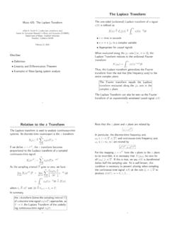
2 The Sigma-Delta converter is inherently an oversampling converter, although oversampling is just one of the techniques contributing to the overall per-formance. Basically, a Sigma-Delta converter digitizes an analog signal with a very low Sigma-Delta CONCEPTS Ideal Topology for Mixed Signal VLSI Chips Oversampling Noise-Spectrum Shaping Using Sigma-Delta Modulator digital Filtering Decimation 16-Bits and Higher Resolution Possible Figure resolution (1 bit)ADC at a very high sam-pling rate. By using oversampling tech-niques in conjunction with noise shaping and digital filtering, the effective resolution is increased. Decimation is then used to reduce the effective sampling rate at the ADC out-put. The Sigma-Delta ADC exhibits excellent differential and integral linearity due to the linearity of the 1 bit quantizer and DAC, and no trimming is required as in other ADC architectures. The key concepts involved in understand-ing the operation of Sigma-Delta converters are oversampling, noise shaping (using a Sigma-Delta modulator), digital filtering, and decimation.
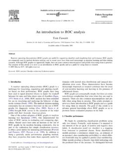
3 0 VERSAMPLING The concept of oversampling has been pre-viously discussed in Section III, and is illus-trated again in Figure and As was NYQUIST SAMPLING WITH ANALOG LOWPASS FILTER ANALOG LOW PASS ~ ADC FILTER ~ass= fa i, s fstop = fs 12 Figure digital SIGNAL L / DATA RA TE = f s OVERSAMPLING WITH ANALOG AND digital FILTERING digital ANALOG LOW PASS FILTER ADC LOWPASS "---r---'L FILTER DECIMATE DATA RATE= Kf8 BYK I 1 DATA RATE = f8~ fstop = Kfs /2 Kfs K = OVERSAMPLING RATIO (INTEGER) rDIGITAL FILTER discussed, one significant benefit of oversam-pling is that the rolloff requirements on the analog antialiasing filter are relaxed. The quantization noi~e (rms value over Nyquist bandwidth is qJ 12 , where q is the weight of the LSB) which falls between f8/2 and kf/2 is removed from the output by the digital filter (k is the oversampling ratio). This has the effect of increasing the overall signal-to-noise ratio by an amount equal to 10log10(k). Unfortunately this is a high price to pay for extra resolution, as an oversampling ratio of 4 is required just to increase the signal-to-noise ratio by a modest ( 1 bit).
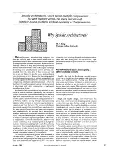
4 'lb keep the oversampling ratio within reasonable bounds, it is possible to shape the frequency spectrum of the quantization noise so that the majority of the noise lies between f /2 and kf/2, and only a small portion is l;ft 2 QUANTIZATION NOISE REMOVED BY digital FILTER Figure between de and fj2. This is precisely what a Sigma-Delta modUlator does in a Sigma-Delta ADC. After the noise spectrum is shaped by the modulator, the digital filter can then remove the bulk of the quantization noise energy, and the overall signal-to-noise ratio (hence the dynamic range) is dramatically in-creased. Sigma-Delta MODULATORS AND QUANTIZATION NOISE SHAPING A block diagram of a first-order sigma -deltaADC is shown in Figure The first part of the converter is the Sigma-Delta modulator which converts the input signal into a continuous serial stream of l's and O's at a rate determined by the sampling clock FIRST -ORDER Sigma-Delta ADC - - --- - - - - - - - - - - - - - - - -1 CLOCK Kf8 LATCHED COMPARATOR (1 BITADC) 1 BIT DATA STREAM Figure digital FILTER AND DECIMA TOR 1 BIT, Kf8 N BITS Sigma-Delta MODULATOR WAVEFORMS \'IN= OV = 2/4 = 4/8 1\l\1\l\l\/\ A/VVVVV\ INTEGRATOR OUTPUT B COMPARATOR OUTPUT 010101010101 COMPARATOR OUTPUT = 3/4 = 6/8 0111011101110 frequency, kf.
5 The 1-bit DAC is driven by the serial output data stream, and the DAC output is subtracted from the input signal. Feedback control theory tells us that the average value of the DAC output (hence the serial bit stream) must approach that of the input signal if the loop has enough gain. The integrator can be represented in the fre-quency domain by a filter whose amplitude response is proportional to 1/f, where fis the input frequency. Since the chopper-like action of the clocked, latched comparator converts the input signal to a high-frequency ac signal, varying about the average value of the input, the effective quantization noise at low frequencies is greatly reduced (the inte-grator looks like a high-pass filter to quanti-zation noise). The exact frequency spectrum of the resulting noise depends on the sam-pling rate, the integrator time constant, and the precise span of the voltage fed back. For any given input value in a single sampling interval, the data from the 1-bit ADC is virtually meaningless.
6 Only when a large number of samples are averaged, will a meaningful value result. The Sigma-Delta modulator is very difficult to analyze in the time domain because of this apparent ran-domness of the single-bit data output. If the input signal is near positive fullscale, it is clear that there will be more l's than O's in the bit stream. Likewise, for signals near negative fullscale, there will be more O's than l's in the bit stream. For signals near midscale, there will be approximately an equal number of l's and O's. Figure shows the output of the integrator for two input conditions. The first is for an input of zero (midscale). To decode the output, pass the output samples through a simple digital lowpass filter that averages every four samples. The output of the filter is 2/4. This value represents bipolar zero. If more samples are averaged, more dynamic range Figure is achieved. For example, averaging 4 samples gives 2 bits of resolution, while averaging 8 samples yields 4/8, or 3 bits of resolution.
7 In the bottom waveform ofFig-ure , the average obtained for 4 samples is 3/4, and the average for 8 samples is 6/8. The Sigma-Delta ADC can also be viewed as a synchronous voltage-to-frequency con-verter followed by a counter. If the number of l's in the output data stream is counted over a sufficient number of samples, the counter output will represent the digital value ofthe input. Obviously,_ this method of averaging will only work for de or very slowly changing input signals. In addition, 2N clock cycles must be counted in order to achieve N-bit effective resolution, thereby severely limiting the effective sampling rate. Further analysis of the Sigma-Delta archi-tecture is best done in the frequency domain using the linear model shown in Figure Note that the integrator is represented as an analog filter with a given transfer function H(O. The transfer function has an amplitude response which is inversely proportional to the input frequency.)
8 The quantizer is mod-eled as a gain stage followed by the addition of quantization noise. One of the advantages of using frequency domain analysis is that algebra can be used to describe the signals. The output value y can be represented as the difference x -y from the summing node at the input multiplied by the transfer function of the analog filter (integrator), multiplied by the gain block, and then added with the quantization noise Q. If we set the gain to 1, and the transfer function is represented as 1/f, the following mathematical relationship results: ~ y = + Q, or by""'rearranging, f y=-x-+ _gf_ f+l f+l FREQUENCY DOMAIN LINEARIZED MODEL OF A sigma delta MODULATOR X + ~ Y= f+1 f+1 H{f) ANALOG FILTER Q =QUANTIZATION NOISE l Figure Note that as frequency f approaches 0, the output approaches x with no noise compo-nent. At higher frequencies, the value ofx is reduced, and the value of the noise compo-nent is increased. For high frequency inputs, the output consists primarily of quantization noise.}
9 In essence, the analog filter has a low pass effect on the signal and a high pass effect on the noise component. For this reason, the analog filter of the modulator can be viewed as a noise shaping filter as shown in Figure 6. 7. SHAPED QUANTIZATION NOISE DISTRIBUTION I I I I I I UJ I 0 : 5 I D. I ~ FREQUENCY I c( ~BAND OF~ INTEREST : I I ' -2-SAMPUNG RATE = Kfs TOTAL AREA =.q/f12 SHAPED QUANTIZATION NOISE FREQUENCY Figure As with analog filters in general, higher order filters offer better performance. This is also true of the Sigma-Delta modulator, provided certain precautions are taken. A second order Sigma-Delta modulator is shown in Figure , and a comparison between the noise shaping functions is shown in Figure Figure shows a plot of the corre-sponding in-band signal-to-noise ratio (dy-namic range) as a function of the oversam-pling ratio for a first and second order modu-lator. Note that the first order transfer function 'has a slope of per octave, while the second order transfer function slope is per octave.)
10 Higher order modulators (greater than second order) can realize even better performance, but the simple linear model must be used with great care, and so-phisticated design techniques are required in order to insure stability. The curve shown in Figure for the third-order loop repre-sents an unrealizable condition and is shown for reference only. The curves in Figure can be used to determine the approximate ADC resolution achievable, given the modulator order and the oversampling rate. For instance, if the oversampling rate is 64x, an ideal second order system is capable of providing a signal to noise ratio of about This implies an ADC resolution of approximately 13 bits. Although the filtering done by the digital filter can be done to any degree of precision SECOND-ORDER Sigma-Delta ADC Figure digital FILTER AND DECIMA TOR desirable, it would be pointless to carry more than 13 binary bits to the outside world. Additional bits would carry no useful signal information, and would be buried in noise.