Transcription of Signal and Power Isolated RS-485 Transceiver with …
1 Signal and Power Isolated RS-485 Transceiver with 15 kV ESD Protection Data Sheet ADM2582E/ADM2587E Rev. G Document Feedback Information furnished by analog devices is believed to be accurate and reliable. However, no responsibility is assumed by analog devices for its use, nor for any infringements of patents or other rights of third parties that may result from its use. Specifications subject to change without notice. No license is granted by implication or otherwise under any patent or patent rights of analog devices .
2 Trademarks and registered trademarks are the property of their respective owners. One Technology Way, Box 9106, Norwood, MA 02062-9106, Tel: 2009 2018 analog devices , Inc. All rights reserved. Technical Support FEATURES Isolated RS-485 /RS-422 Transceiver , configurable as half or full duplex isoPower integrated Isolated dc-to-dc converter 15 kV ESD protection on RS-485 input/output pins Complies with ANSI/TIA/EIA-485-A-98 and ISO 8482:1987(E) ADM2582E data rate: 16 Mbps ADM2587E data rate: 500 kbps 5 V or V operation Connect up to 256 nodes on one bus Open- and short-circuit, fail-safe receiver inputs High common-mode transient immunity.
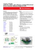
3 >25 kV/ s Thermal shutdown protection Safety and regulatory approvals UL recognition: 2500 V rms for 1 minute per UL 1577 VDE Certificates of Conformity DIN EN 60747-5-2 (VDE 0884 Part 2): 2003-01 VIORM = 560 V peak Operating temperature range: 40 C to +85 C Highly integrated, 20-lead, wide-body SOIC package APPLICATIONS Isolated RS-485 /RS-422 interfaces Industrial field networks Multipoint data transmission systems FUNCTIONAL BLOCK DIAGRAM ADM2582E/ADM2587 ETxDABYZDEVCCRxDREISOLATIONBARRIERTRANSC EIVERGND1 GND2 ENCODEENCODEDECODEDECODEDRDECODEENCODEOS CILLATORRECTIFIERREGULATORVISOOUTDIGIT AL ISOL ATIONiC ouplerisoPower DC-TO-DCCONVERTERVISOIN08111-001 Figure 1.
4 GENERAL DESCRIPTION The ADM2582E/ADM2587E are fully integrated Signal and Power Isolated data transceivers with 15 kV ESD protection and are suitable for high speed communication on multipoint transmission lines. The ADM2582E/ADM2587E include an integrated Isolated dc-to-dc Power supply, which eliminates the need for an external dc-to-dc isolation block. They are designed for balanced transmission lines and comply with ANSI/TIA/EIA-485-A-98 and ISO 8482:1987(E). The devices integrate analog devices , Inc.
5 , iCoupler technology to combine a 3-channel isolator, a three-state differential line driver, a differential input receiver, and analog devices isoPower dc-to-dc converter into a single package. The devices are powered by a single 5 V or V supply, realizing a fully integrated Signal and Power Isolated RS-485 solution. The ADM2582E/ADM2587E driver has an active high enable. An active low receiver enable is also provided, which causes the receiver output to enter a high impedance state when disabled.
6 The devices have current limiting and thermal shutdown features to protect against output short circuits and situations where bus contention may cause excessive Power dissipation. The parts are fully specified over the industrial temperature range and are available in a highly integrated, 20-lead, wide-body SOIC package. The ADM2582E/ADM2587E contain isoPower technology that uses high frequency switching elements to transfer Power through the transformer. Special care must be taken during printed circuit board (PCB) layout to meet emissions standards.
7 Refer to the AN-0971 Application Note, Control of Radiated Emissions with isoPower devices , for details on board layout considerations. ADM2582E/ADM2587E Data Sheet Rev. G | Page 2 of 22 TABLE OF CONTENTS Features .. 1 Applications .. 1 Functional Block Diagram .. 1 General Description .. 1 Revision History .. 2 Specifications .. 4 ADM2582E Timing Specifications .. 5 ADM2587E Timing Specifications .. 5 ADM2582E/ADM2587E Package Characteristics .. 5 ADM2582E/ADM2587E Regulatory Information .. 6 ADM2582E/ADM2587E Insulation and Safety-Related Specifications.
8 6 ADM2582E/ADM2587E VDE 0884 Insulation Characteristics .. 6 Absolute Maximum Ratings .. 7 ESD Caution .. 7 Pin Configuration and Function Descriptions .. 8 Typical Performance Characteristics .. 9 Test Circuits .. 13 Switching Characteristics .. 14 Circuit 15 Signal Isolation .. 15 Power Isolation .. 15 Truth 15 Thermal Shutdown .. 15 Open- and Short-Circuit, Fail-Safe Receiver 15 DC Correctness and Magnetic Field Immunity .. 15 Applications Information .. 17 PCB Layout and Electromagnetic Interference (EMI).
9 17 Insulation Lifetime .. 18 Isolated Power Supply Considerations .. 19 Typical Applications .. 20 Outline Dimensions .. 22 Ordering Guide .. 22 REVISION HISTORY 5/2018 Rev. F to Rev. G Changes to Table 10 .. 8 Deleted Electromagnetic Interference (EMI) Considerations Section .. 16 Changes to PCB Layout and Electromagnetic Interference (EMI) Section .. 17 Changes to Figure 35 .. 18 Changes to PCB Layout Reference .. 19 Changes to Ordering Guide .. 22 9/2016 Rev. E to Rev. F Changes to Ordering Guide.
10 20 10/2014 Rev. D to Rev. E Changes to Table 12 .. 14 9/2014 Rev. C to Rev. D Changes to Figure 9 .. 9 6/2011 Rev. B to Rev. C Changes to Features Section and Figure 1 .. 1 Changes to Table 4 .. 4 Changes to Table 5 .. 5 Deleted Table 6; Renumbered Sequentially .. 5 Added Thermal Resistance JA Parameter, Table 8 .. 6 Changes to Table 9 .. 6 Changes to Table 10 .. 7 Changes to Table 13 .. 14 Moved DC Correctness and Magnetic Field Immunity Section .. 14 Changes to PCB Layout Section and Figure 35.