Transcription of Signal Limiter for Power Amplifiers - THAT …
1 The circuits within this application note feature THAT4301 Analog Engine to provide theessential elements of voltage-controlled amplifier (VCA) and rms-level detector (RMS). Sincewriting this note, that has introduced several new models of Analog Engines, as well as newVCAs. With minor modifications, these newer ICs are generally applicable to the designs shownherein, and may offer advantages in performance, cost, Power consumption, etc., depending onthe design requirements. As well, a standalone RMS is available to complement our standaloneVCAs. We encourage readers to consider the following alternatives in addition to the 4301: Low supply voltage and Power consumption: 4320 Low cost, supply voltage, and Power consumption: 4315 Low cost and Power consumption: 4305 High-performance (VCA only): 2180-series, 2181-series Dual (VCA only): 2162 RMS (standalone): 2252 For more information about making these substitutions, please contact that Corporation'stechnical support group at Note 03(formerly Application Note 103) that Corporation; 45 Sumner Street, Milford, Massachusetts 01757-1656; USATel: +1 (508) 478-9200; Fax: +1 (508) 478-0990; Web.
2 Email: 2009, that Corporation; All rights reserved. Document 600034 Revision 02 Signal LimiterforPower AmplifiersThe simplest circuits used to prevent overloadin Power Amplifiers usually employ diode have the advantages of being both fast andinexpensive. They also sound quite unpleasantwhen the amplifier is overdriven for more than afew tens of milliseconds. As a result, users mayavoid fully exploiting the amplifier s availableheadroom because they fear the sonic results ofoverload. In the worst case, an amplifier withotherwise admirable performance may gain areputation for poor sound significantly improved version shown hereemploys two stages of protection a VCA-basedlimiter which quickly and automatically reduces theinput Signal level to just below the overload point,and a conventional diode clipper to handle anyshort duration excursions while the Limiter circuits shown are built around the THAT4301 Analog Engine.
3 The that 4301 provides asingle-chip solution for a variety of analog signalprocessing applications. It includes a high qualityBlackmer gain-cell VCA, an RMS-level detector, andthree general purpose op amps, two of which areundedicated. The circuits shown are easily adapt-able for use with separate that Corporation VCAsand RMS-level detectors where even higherperformance is will approach the design of the circuit usingan approximately real-world example with thefollowing assumptions:1. The Power amplifier s decibel voltage gain is32 dB, a common value;2. The maximum average Power that can be dissi-pated by the 8 load is 600 W;3.
4 The maximum peak Power that can be dissi-pated by the 8 load is 6 these assumptions, we make the followingcalculations:1. The voltage gain of the Power amplifier isAV=103220l402. Assuming a sine wave output, the output voltage atmaximum average Power dissipation isVoutmaxavg P=600W%8 =70 VRMS3. The output at maximum peak Power dissipationis: Vinmaxpeak P=6000W%8 =220 VRMSK nowing these values, we can calculate the appropri-ate Limiter and clipper output voltages asVinmaxavg P=70 VRMS40= Vinmaxpeak P=220 VRMS40= Limiter for Power AmplifiersPower Amplifiers , when driven out of theirlinear range of operation, sound particularlybad, and can produce damage to themselves orthe transducers to which they are design of traditional protection circuitsis complicated by the various performance,cost, and sonic tradeoffs involved.
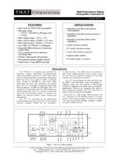
5 There iscertainly no one right answer to the limiterpuzzle. The circuits presented here, however,are designed to maintain a high level of sonicintegrity, while remaining circuits combine active limiting with adiode-based clipper to provide excellent driverprotection while avoiding the sonic degradationof simpler designs. An innovative nonlinearcapacitor circuit further improves the sonicperformance of the design is based on the that 4301 Analog Engine , and thus requires only a singleIC, a couple of transistors and diodes, and ahandful of passive Note 03(Formerly Application Note 103) that Corporation; 45 Sumner Street; Milford, MA 01757-1656; USATel: +1 508 478 9200; Fax: +1 508 478 0990; Email: Web: 2009, that Corporation; Document 600034 Rev 02 Signal Limiter for Power ApplicationsThe circuit shown in Figure 1 demonstrates thebasic feedback Limiter with adjustable clipper.
6 Theinput Signal is fed to the Limiter circuitry at thenode labeled Input . The Limiter s output is sentto the Power amplifier from the point labeled ToPower amplifier . In addition, the output from thepower amplifier is fed back to the Limiter circuit byway of the node marked From Power AmplifierOutput .Under normal operation, the input Signal isbelow the Limiter s threshold and so the VCA is atunity gain, its lowest distortion peak output levels of short duration whichexceed the predetermined clip level, the clippercircuit hard limits the output to this level,performing very much like the (adjustable) diodeclipper that it is.
7 If the output level remains abovethreshold for long, the Signal s rms value willexceed the Limiter s average Power threshold,causing the Limiter to quickly reduce the level ofsignal being fed to the amplifier . In this way,inaudible (but potentially damaging) peaks of shortduration will be clipped, while longer durationpeaks will be handled by the Limiter , and littleaudible impairment should ClipperFigure 2 shows the clipper circuit used in thisdesign. A trans-impedance amplifier , OA3,converts the output current from the VCA to avoltage which drives the actual clipper OA3 s output voltage exceeds the thresholdset by VR1, the transistor pair Q1 and Q2 combineto bypass R2 and clip the output to a fixed 600034 Rev 02 Page 2 of 8 Design Note 03 Signal Limiter for Power AmplifiersTHAT Corporation; 45 Sumner Street; Milford, MA 01757-1656; USATel: +1 508 478 9200; Fax: +1 508 478 0990.
8 Email: Web: 2009, that Corporation12OA3IN17 OUTU1A4301 PIT2CT5IN1 OUT4 RMSD etectorU1B4301P687OA2U1C4301P181920OA1U1 D4301PR120kR220kR551RR6300kR92MR1010kR13 4k99R14100kR81M2R1210kC2220uVR350kC322uC 422u-15D11N4148D21N4148+15-15VR450kC1147 p+15-15+15-15C7100nInputTo Power Amp InputC1322nThresholdAmplifierControl Port BufferMake-up Gain AdjustmentSymmetryAdjustment+20dB-20dBQ1 2N3904Q22N3906VR120kR310kR410k-15 StereoConnectionR791kR15820kVR250kFrom Power AmpOutputZero dB Reference LevelD31N4148D41N4148R1675kR1110kC6220uE C+SYMEC-V+V-GND1691013111415 Clipper Circuit+15 VCAF igure 1. Schematic of basic Signal limiterBasic Feedback Limiter with Diode ClipperUsing our design example, the peak allowablepower is specified as 220 VRMS, and since we areultimately clipping the Signal to a square wave, thisis equivalent to 220 Vpeak.
9 Given the Power ampli-fier s gain of 40, the Limiter must clip at two 1N4148 diodes prevent base-emitterbreakdown in Q1 and Q2. The addition of thesediodes means that the clipping voltage will be twodiode drops (approximately V) greater than thevoltage at the bases of Q1 and Q2. VR1 adjusts thevoltage at the base of Q1 between 0 and V, andat the base of Q2 between 0 and + V. Since wewant the Limiter to clip at V, VR1 should beadjusted to provide V and V at the bases ofQ1 and Q2, LimiterTo form the Limiter block, the VCA in Figure 1is configured as a high-compression-ratio feedbackcompressor.
10 Under normal operation, the ampli-fier output is below the compressor s thresholdvoltage, the VCA s EC- control port is kept at zerovolts, resulting in no compression or limitingaction. Above the threshold level, the thresholdamplifier conducts and closes the feedback loopfrom the RMS level-detector to the VCA, resulting inthe desired Limiter 3 shows a simplified diagram of afeedback (FB) compressor. By inspection, , AndVout dB=Vin dB+GdB , WhereGdB= A%Venc dB1. Vin dB is the input level in decibels and Vout dB isthe output level in decibels,2. GdB is the VCA gain in decibels, and3.