Transcription of SILENCER SELECTION - Vibro Acoustics
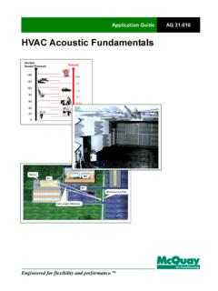
1 For general information in hvac Acoustics , consult the following publications: >2017 ASHRAE Fundamentals Handbook, Chapter 8 Sound and Vibration >2015 ASHRAE Applications Handbook, Chapter 48 Noise and Vibration Control >Algorithms for hvac Acoustics , 1991 >A Practical Guide to Noise and Vibration Control for hvac Systems, 1991 Before following the procedures below, it may be beneficial to first familiarize yourself with the 18 Common Silencing Problems summarized and illustrated through SILENCER Application Solutions (SAS sheets) found in the Application section of the this select a SILENCER , it is necessary to determine:How much insertion loss (IL) is necessary to achieve the specified room sound criterionHow much additional pressure drop (PD) is allowable at the system duct velocityWhere the SILENCER should be locatedHow much SILENCER airflow generated noise (GN) can be toleratedSilencer type to meet system/application requirementsSilencer model to meet IL, PD and GN requirementsSilencer constructionSILENCER SELECTION INSTRUCTIONS123456711-800-565-8401 | | Insertion Loss RequiredEACH DUCT SYSTEM needs to be analyzed separately.
2 All possible sound sources and paths should be considered. Common paths often forgotten include duct break-out noise and equipment noise radiated to the environment through intake or exhaust is critical that the duct system analysis begin at the initial sound source and continue in order, duct element by element, to the occupied space. This will ensure that the noise level can be calculated at any point along the system to help determine if break-out noise and/or airflow generated noise need to be controlled (see below).The octave band sound power levels of the noise generating elements are summed logarithmically ( main fan or AHU, terminal boxes and airflow generated noise of ductwork, fittings, terminal devices, etc.). The natural attenuation elements, such as ductwork, plenums and fittings, etc. are subtracted. (See ASHRAE s System Design Procedures 1 for more details.)The SILENCER should not be included in the initial calculation. Its required insertion loss is the positive difference between the estimated resultant sound pressure level in the space and the room criterion2 for the space.
3 If a duct system transmits noise to more than one space, the greatest insertion loss for each octave band is the insertion loss V-A Select computer program automates the duct system analysis procedure. See the V-A Select manual for more ASHRAE Applications Handbook, 2015, P. Applications Handbook, 2015, P. Maximum Allowable Pressure DropDETERMINE how much SILENCER pressure drop (including system effects) has been allowed for in the system design. Ordinarily, the SILENCER pressure drop (including system effects) should not exceed (85 Pa).1 The user should always consider the added losses due to aerodynamic system effects. That is, if the SILENCER is located where less than ideal conditions at the inlet and/or at the discharge of the SILENCER exist, then the SILENCER s effective pressure drop will be increased. (Total SILENCER PD = SILENCER PD per catalog ASTM E-477-13 rating + system effect losses). In some situations the added system effect losses can exceed the pressure drop of the : Effect of SILENCER Location on Pressure Drop PerformanceFor example, an elbow fitting located immediately following a SILENCER will prevent regain of static pressure from the SILENCER s exit velocity pressure.
4 Furthermore, local velocities within the elbow fitting will be greater than the average duct velocity and more turbulent. These factors will produce higher overall static pressure Applications Handbook, 2015, P. SELECTION INSTRUCTIONS1A5AA221-800-565-8401 | | THE FOLLOWING are guidelines to estimate increased pressure losses due to varying SILENCER inlet and discharge conditions. These should be considered only as very approximate guidelines. Substantial variations can occur depending upon the type of SILENCER , its internal geometry, size of SILENCER , size of duct, airflow turbulence, : the factors shown do NOT include pressure drops of the duct element. These must be added SYSTEM EFFECTSTo determine the allowable SILENCER catalog pressure drop for SELECTION and specification purposes:Allowable Catalog SILENCER PD =Total Allowable SILENCER Pressure Drop including System Effects(Inlet System Effect Factor x Outlet System Effect Factor) Vibro - Acoustics V-A Select program allows the user to evaluate system effects when selecting silencers .
5 See the V-A Select Manual for more ElementSilencer system effect factor duct element InletSilencer DischargeTransitions7-1/2 degrees per sideDistance of transition from silencerD1 = 1 D = 2D = 325 degrees per sideDistance of transition from silencerD = 1 D = 2D = 345 degrees per sideDistance of transition from silencerD = 1 D = 2D = ..11 .11 .11 .11 .11 .11 .11 .1 Elbow radius typeDistance of radius elbow from silencerD = 0D = . mitered type with short turning vanesDistance of mitered elbow from silencerD = 0 D = 1D = .11 . D is the diameter of round duct or equivalent diameter of rectangular | | Duct ElementSilencer system effect factor duct element InletSilencer DischargeElbow mitered type with no turning vanesDistance of mitered elbow from silencerD1 = 0 D = 1D = . entry or exitSmooth Inlet or DischargeDistance of entry or exit from silencerD = 0D = 1D = 2D = 31 .. entry or exitSharp Inlet or DischargeDistance of entry or exit from silencerD = 0 D = 1 D = 2 D =.
6 FanDistance of centrifugal fan from silencerD = 0 D = 1D = 2 D = . fan (Also see below effect of SILENCER on fan)Distance of axial fan from silencerD = 0 D = 1D = 2 D = . D is the diameter of round duct or equivalent diameter of rectangular SYSTEM EFFECTS41-800-565-8401 | | Duct ElementSilencer system effect factor duct element InletSilencer DischargeCoils or filtersDistance of coils or filters from silencerD1 = 0 D = 1D = .11 D is the diameter of round duct or equivalent diameter of rectangular DIAGRAM1 Inlet Cone SILENCER must be aerodynamically matched to fan hub, otherwise consumed increases considerably to 105% - 110% or more!Axial/Fan SILENCER System EffectsThe effects of various Free Air SILENCER Inlets/Discharges upon horsepower consumed by an Axial Fan in a Constant System with Constant Air Flow. Percentages are indicative only, and would differ in different Notes: A. If a fan consumes less horsepower, it generates less noise and therefore needs less Turbulence allowed to impinge upon the plane of the axial fan blades can create 10-15 dB or more excess fan sound CONSUMEDFREE DISCHARGES tandard Bellmouth InletInlet cone SILENCER well matched to fan hub acoustic plenumPlenum with aerodynamic low turbulence splittersPlenum with blunt turbulent splitters100%97%97%99%104%100%99%105%106 %110%Abrupt fan discharge to roomFan manufacturer s evaseDischarge cone SILENCER well matched to fan motor hub Non-aerodynamic evase (typical) & aerodynamic splittersNon-aerodynamic evase (typical)
7 & blunt non-aerodynamic splittersConstantSystemConstantSystemCon stantSystemConstantSystemConstantSystem1 425362 Splitters designed so turbulent wake is gone before reaching plane of the fan blades, for lowest fan Blunt, untapered splitters with either radius or sharp edged tails, create excess turbulence & fan noise from Although unlikely in practice, this was chosen as the reference Discharge Cone silencers must be matched to fan motor hub, or fan can be well in excess of 100%!6 Blunt, untapered splitters do not allow pressure/velocity recovery before dumping air to the room causing excessive, abrupt expansion pressure SYSTEM EFFECTS51-800-565-8401 | | Considerations for SILENCER LocationBEST SILENCER LOCATION IF NO FIRE DAMPERBEST SILENCER LOCATION IF FIRE DAMPER IS REQUIREDALTERNATE SILENCER LOCATIONS ilencer LocationSILENCERS SHOULD generally be located as close to the fan or noise source as possible. This will help contain the noise at the source and limit potential points along the system where the unsilenced noise may break out.
8 However, turbulent airflow usually exists close to noise sources such as fans, valves, dampers, etc. Therefore the user should evaluate aerodynamic system effects (see above).If silencers are carefully designed they can actually improve flow conditions close to fans. Special fan inlet and discharge silencers , including cone silencers and inlet box silencers , minimize aerodynamic system effects, and contain noise at the source. Their effective added pressure drop could even be slightly negative if the SILENCER improves the flow into or out of the fan, thus increasing the fan s the foregoing, the best acoustic location for a duct SILENCER may be straddling the mechanical room wall to minimize ductborne and breakout/break-in noise (see figure). However, fire dampers are often located at this point. As a compromise, many times silencers are located inside the mechanical room close to the mechanical room wall. However, if space does not permit this position, the SILENCER may need to be located outside the mechanical room.
9 In such cases, high transmission loss (HTL) SILENCER walls may be required to prevent noise from breaking in or out of the SILENCER before it is fully attenuated. Connecting duct between the SILENCER and wall may also have to be HTL wall roomOccupied spaceSILENCERM echanical roomOccupied spaceSILENCERFDM echanical roomOccupied spaceSILENCERFDH eavier SILENCER walls may be required to stop breakout noiseSILENCER SELECTION INSTRUCTIONS61-800-565-8401 | | Maximum Allowable Airflow Generated NoiseIN THE MAJORITY OF INSTALLATIONS, a concern for SILENCER airflow generated noise is generally unwarranted because it does not materially contribute to the overall system noise level. This is particularly true if the SILENCER is properly located close to the source and pressure drops are not recommends that in general, airflow generated noise should be evaluated if SILENCER static pressure drops exceed (including system effects), the noise criterion is below RC-35(N), or if the SILENCER is located very close to or in the occupied roughly calculate the maximum allowable SILENCER generated noise when the SILENCER is located very close to or in the occupied space: Subtract 5dB per octave from the room sound criterion : ASHRAE does not recommend selecting silencers with pressure drops in excess of pressure drop (including system effect).
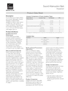
10 If the noise criterion is below RC-35(N) consider retaining a qualified Acoustical Consulting Engineer having expertise in hvac noise Type of SilencerONCE THE ABOVE STEPS HAVE BEEN FOLLOWED, DETERMINE: > SILENCER shape (Rectangular or Circular dependent on the connection shape of the ductwork). > SILENCER type >Dissipative (RD and CD): Uses acoustic grade glass fiber protected by perforated metal. >Film-Faced (RFL and CFL): Dissipative type with film such as Tedlar or Mylar lining between the perforatedmetal and the acoustical glass fiber. An acoustical spacer is used between the perforated metal and the liner to reduce insertion loss degradations caused by the film liner. >No-Media (RNM, CNM and CENM): Completely void of absorptive media or fill of any kind. 3 ASHRAE Applications Handbook, 1995 p. SELECTION INSTRUCTIONS4571-800-565-8401 | | SILENCER SELECTION INSTRUCTIONSN ormal Recommended Duct Velocity Ranges for Vibro - Acoustics SilencersUltra Low VelocityLow VelocityMedium VelocityHigh Velocity Ultra High VelocitySilencer TypeU LVLVMVHVUHVRD, RFL, RNM0-500 fpm500-750 fpm750-1250 fpm1250-2000 fpmsee SS8 and SS9CD, CFLsee LV0-1500 fpm1500-3000 fpm3000-5000 fpm5000-7000 fpmCNM see LV0-750 fpm750-1250 fpm1250-2000 fpm2000-3500 fpmCENMsee LV0-1250 fpm1250-1750 fpm1750-2250 fpmN/ANote: silencers can always be used in systems with lower velocities than the recommended operating range.