Transcription of SILVER BULLET SERIES MODELS 316, 316DB & 316SB ...
1 SILVER BULLET . SERIES MODELS 316, 316DB &. 316SB INSTALLATION. AND OPERATIONS MANUAL. IOM: Tech-167 Revision: C. Prepared By: Date: 5/27/98 Drafting Work Order:21104 ECN: 12621. Reviewed By: Date:11/21/14 Approved By: Date:11/20/14. This IOM contains confidential information and is issued in confidence on the condition that it be returned on demand and not be copied, reproduced, disclosed to others or used in manufacture of the subject matter thereof without the written consent of Westlock Controls WESTLOCK CONTROLS CORPORATION. 280 N. MIDLAND AVE., STE. 258, SADDLE BROOK, NJ 07663 TEL: 201-794-7650 FAX: 201-794-0913. 5/27/98 TECH-167 17003 Page 1 of 6. Revision History Revision Initial release 5/27/98 11/1/05 1/11/11 10/16/14. Westlock Controls Offices USA. Westlock Controls Corp. 280 North Midland Ave, Suite 258, Saddle Brook, NJ 07663. Phone: (201) 794-7650 Fax: (201) 794-0913. Email: Internet Europe Westlock Controls UK.
2 22 Chapman Way, Tunbridge Wells Kent, England TN23EF. Phone: 011-44-189-251-6277 Fax: 011-441-892-516279. Email: Internet: South America Westlock Equipamentos de Controle Ltda. Sales: Operations: Al. Araguaia, 2044 Sl. 1101, Bloco B Av. Antonio Bardella, 3000. Edif cio CEA Alphaville Galp es 2A e 2B Alto da Boa Vista Barueri S o Paulo Brazil Sorocaba S o Paulo Brazil 06455-000 18085-852. Tel: + 55 11 2588-1400 Tel: + 55 15 2102-7400. Fax: + 55 11 2588-1410 Fax: + 55 15 2102-7400. Email: Internet: Asia Westlock Controls Singapore Sales: King's Centre #04-01. 390 Havelock Road Singapore 169662. Phone: +65 676 858 00 Fax: 011-441-892-516279. Email: Internet: WESTLOCK CONTROLS CORPORATION. 280 N. MIDLAND AVE., STE. 258, SADDLE BROOK, NJ 07663 TEL: 201-794-7650 FAX: 201-794-0913. 5/27/98 TECH-167 17003 Page 2 of 6. 1. Introduction Product Certification ITS 10 ATEX16970X. Ex II 2GD Ex d IIC T* Gb Ex tb IIIC T* Db IP6X. IECEx ITS Ex d IIC T* Gb Ex tb IIIC T* Db IP6X.
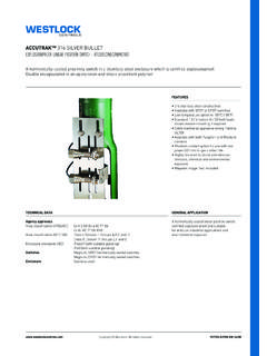
3 Ta = -20 C TO 84 C T5 and -20 C TO +69 C T6. Class I, Division 1, Groups A, B, C & D. Class II, Division 1, Groups E, F & G. -50 C to 85 C T6. Warnings Never remove enclosure cover or make/break electrical connections with power connected to the unit. Perform all wiring in accordance with site and local codes and the National Electric Code ANSI-NFPA-70 (US) or the Canadian Electric Code Part I (Canada) for the appropriate area classifications. Confirm that the AccuTrak model being installed is approved for the hazardous area (see Product Certification section above or unit ID. label). Confirm that supply power to switches is within rated specifications listed on the unit identification label. Protect the unit from exposure to aggressive substances or atmospheres to ensure that hazard rating is not compromised. Description The Westlock SILVER BULLET SERIES products are hermetically sealed, dry contact, single pole double throw or double pole double throw reed switch element encapsulated in a 316 stainless steel casing with epoxy resin and shock absorbent polymer.
4 The SILVER BULLET 316DB features an integral, 7- conductor cable, and the SILVER BULLET 316 features an integral, 4-conductor cable. conduit entry and externally threaded casing for ease of mounting and position adjustment. It is also supplied with threaded, encapsulated magnetic triggering bolts that facilitate adjustment of the gap between SILVER BULLET and the triggering mechanism. Principles of Operation The SILVER BULLET SERIES 316 operates on the principle of magnetic attraction, reacting to ferromagnetic actuators as they come within the switch's sensing range. WESTLOCK CONTROLS CORPORATION. 280 N. MIDLAND AVE., STE. 258, SADDLE BROOK, NJ 07663 TEL: 201-794-7650 FAX: 201-794-0913. 5/27/98 TECH-167 17003 Page 3 of 6. All sensors, when actuated by the presence of a ferromagnetic trigger, change the state of electrical contacts from Normally Closed (N/C) to Normally Open (N/O). Special Features IECEX/ATEX CONDITIONS OF SAFE USE: 1.
5 Encapsulating compound must be protected from UV radiation 2. Cable entry thread is either or 1/2-14 NPT. 3. Only suitably approved cable glands may be used. 4. When conduit is used, a suitably approved stopping box must be installed within 1/2 inch ( ) of conduit opening. 5. Metal casing of product must be suitably grounded or equipotentially bonded unless using grounded metal conduit. 6. WARNING: DO NOT OPEN PRODUCT WHEN ENERGIZED OR WHEN. AN EXPLOSIVE ATMOSPHERE IS PRESENT. All Magnum SILVER Bullets are Hermetically sealed. For installation in hazardous locations, check local electrical codes. Seal fitting not required. 2. Order Guide See applicable catalog literature for ordering guide. 3. Definitions Not applicable 4. Installation Mounting Determine the actuator(s) and trigger(s) desired operating point. Locate switch and/or actuator to assure that actuator comes within switch's sensing area. -Use ferromagnetic trigger furnished with each sensor.
6 -Avoid contact between switch and actuator, which may damage switch. Switches must be mounted as follows: The blue arrow on the DPDT switch must be oriented in the same direction as the travel of the trigger. -When mounting switches side-by-side, sensing areas must face the same direction. WESTLOCK CONTROLS CORPORATION. 280 N. MIDLAND AVE., STE. 258, SADDLE BROOK, NJ 07663 TEL: 201-794-7650 FAX: 201-794-0913. 5/27/98 TECH-167 17003 Page 4 of 6. -When mounting switches with sensing areas facing each other, install them at least 3 inches apart. For best results, utilize the ferromagnetic trigger supplied with each sensor. -Keep all magnetic materials at least 1 inch away from switch. -Steel placed inside the switch's differential area will not affect functioning. SILVER BULLET Blue arrow marking on DPDT. MODELS designates the required direction for the travel of the trigger Ferromagnetic Trigger Calibration -Align magnetic trigger axially with the sensing end of the SILVER BULLET .
7 Adjust gap between magnetic trigger bolt to approximately inch from the SILVER BULLET . Note: Be sure to abide by orientation instructions provided in the mounting section with regards to the direction of travel of the trigger to ensure best switch performance. -Connect leads of a suitable continuity tester to the black (normally open contact) and white (common contact) wires of the SILVER BULLET (refer to wiring diagram). - Verify continuity between black and white wires in the presence of the trigger. Repeat continuity test between the brown and blue wires in the presence of the trigger for DPDT MODELS . Note: If an open circuit is required when the SILVER BULLET is triggered, connect continuity tester to the red (normally closed contact) and white (common contact) wires and to orange (normally closed contact) and blue (common contact) wires for DPDT MODELS , and follow the above continuity verification in the presence of the trigger.
8 4. Field Wiring Attach conduit or cable correctly -When using long runs of conduit or cable, place supports close to the switch to avoid pulling switch out of position. -For installation in hazardous locations, check local electrical codes. 5. Maintenance and Repair No maintenance is required for 316 SERIES products. WESTLOCK CONTROLS CORPORATION. 280 N. MIDLAND AVE., STE. 258, SADDLE BROOK, NJ 07663 TEL: 201-794-7650 FAX: 201-794-0913. 5/27/98 TECH-167 17003 Page 5 of 6. 6. Appendix Mechanical Full Metal Outer Jacket: 316 Stainless Steel Hermetic Seal: Glass (Inert gas). Potting: Epoxy Resin Contacts: Tungsten or Rhodium (specify model No.). Type Rating: N/A. IP Rating: 65, 67. Std. Temp. Range ( F) ( C): -40 F to 220 F, -40 C to 104 C. Low Temp. Range ( F) ( C): -58 F to 185 F, -50 C to 85 C. Operational Life: 600,000 cycles (full rated load). Sensor Actuation: Ferromagnetic Sensing Distance: ( ) end sensing Electrical Contact Arrangement: DPDT, Form CC (normally open) or SPDT, Form C (normally open) as specified by model number Contacts: Solid Tungsten or rhodium as specified by model number Current Rating: Tungsten: 3 Amps/120 VAC, 2 Amps/ 24 VDC; Rhodium: 1 Amp/24 VDC.
9 Operating time: m Sec. Initial Contact .50 ohms (Max.). Resistance: Repeatability: .005 in. Hysteresis: .040 in Conduit Connection: 1/2''-14 NPT or M20 X Factory Sealed with 48 min. length, 7 Conductor (DPDT) or 4 Conductor (SPDT) PVC Insulation, rated for Leads (Std): 105 C at 600V. Leads (Low Temp Factory Sealed with 48 min. length, 7 Conductor (DPDT) or 4 Conductor (SPDT) XL PE/TPE Insulation, Option): rated for 125 C at 300V. DPDT, Form CC (Normally Open) 3 Amps/120 VAC, 2 AMPS/ 24 VDC wire: 7 Conductor, 18 AWG, Ground Contact Ratings: SPDT, Form C (Normally Open) 3 Amps/120 VAC, 2 AMPS/ 24 VDC wire: 4 Conductor, 18 AWG, Ground: Green , NC: Red, NO: Black, Common: White Wiring Diagram for SPDT MODELS : Dimensional Data: Wiring Diagram for DPDT MODELS : WESTLOCK CONTROLS CORPORATION. 280 N. MIDLAND AVE., STE. 258, SADDLE BROOK, NJ 07663 TEL: 201-794-7650 FAX: 201-794-0913. 5/27/98 TECH-167 17003 Page 6 of 6.