Transcription of Silvertone Radio (parts list and instruction) (Sears)
1 PARTS LIST AND INSTRUCTIONS FOR INSTALLING AND OPERATING YOUR Radio WITH AUTOMATIC RECORD CHANGER WHEN ORDERING CHASSIS PARTS OR WRITING US ABOUT THIS Radio , ALWAYS GIVE THE CHASSIS NUMBER INDICATED ON THE METAL TAG (PICTURED ABOVE) ON THE CHASSIS AND THE CATALOG NUMBER SHOWN ON THE CABINET STICKER. , PLEASE READ THESE INSTRUCTIONS VERY CAREFULLY BEFORE OPERATING YOUR Radio . THE INSTRUCTIONS TELL YOU: 1 HOW TO INSTALL AND OPERATE YOUR Radio PROPERLY SO THAT YOU WILL HAVE THE FINEST POSSIBLE RECEPTION. 2 HOW TO KEEP YOUR Radio IN GOOD CONDITION. 3 HOW TO OBTAIN PROPER SERVICE ATTENTION SHOULD YOU EVER REQUIRE IT. IF YOU FOLLOW THE INSTRUCTIONS CAREFULLY YOU WILL BE ASSURED Of THE 'fiNE PERFORMANCE AND CONTINUED SATISfACTION BUILT INTO ALL Silvertone RADIOS.
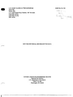
2 SEARS, ROEBUCK AND COMPANY KEEP THIS BOOKLET. IT CONTAINS VALUABLE SERVICE INFORMATION INSTALLATION PREPARING THE RECEIVER FOR INSTALLATION PREPARING THE RECORD CHANGER FOR OPERATION Do not connect this unit to a power outlet until all shipping items as in dicated in the illustrations and paragraphs below have been removed. Remove the two (2) red painted screws inserted at an angle at the rear of the Radio chassis. These parts may be reached through the back of the cabinet. (See illustration be low. ) Remove the red painted screws and wood block that hold the record changer drawer closed. (See illustration below.) REMovE TWO wOOD SCREWS~------' (PAINTED RED) GREEN LEAD (fROM RECEIVER) BLACK LEAD EXTER NAL fM antenna LEADS (300 OHM LINE) BUILT -IN FM antenna CONNECTED HERE AM antenna DISCONNECT WHEN USING CONNECTOR EX TERNAL fM ANTE N NA REMOVE RUBBER GROMMET AND LIFT RECORD SUPPORT ARM KNOB-,"'.
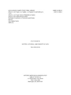
3 LIFT UP PACKING FLAPS REMOVE TURNTABLE REMOVE TURNTABLE SHIPPING SUPPORT WHEN MOUNTING PLATE TURN(Z) HOLDDDWN SCREWS IS fLOATING, REMOVE (LARGE ROUND HEAD SCREWS) CLOTH TAPE . CLOCKWISE AS fAR AS POSSIBLE REMOVE PACKING REPLACE TURNTABLE RECORD SUPPORT ARM KNOB The record changer is floated on spring mountings. For shipping purposes only, these mountings are made rigid. To float the changer, remove the turntable by lifting it straight up the spindle. Turn the two holddown screws (identified by large, round heads) in a clockwise direction as far as possible and replace the turntable. Replace the turntable with a clockwise turning motion, making sure that the driver wheel is in position against the inside flange of the turntable.
4 Remove needle guard from pickup cartridge. PAGE 2 TUBES RECORD CHANGER CONNECTION LOCATION POWER SUPPLY antenna AND GROUND CONNECTIONS FOR UNUSUAL CONDITIONS It is essential to have the record changer absolutely level. Use a tor pedo or sirllilar type level on the record changer baseplate. Use ade quate shims under the Radio cabinet to achieve perfect level. CAUTION: REMOVE THE ELECTRIC OR POWER CORD FROM THE WALL OR FLOOR OUTLET BEFORE REPLACING TUBES, REMOVING, ADJUSTING, OR CLEANING THE CHASSIS OR WHILE CONNECTING AN AERIAL WIRE. The receiver is shipped with the tubes in their proper sockets. See that the tubes are firmly pushed down in their sockets and the tube shield on the 6X8 tube is in place.
5 (See illustration on Page 14). See that the connectionsfrom the pickup arm and from the turntable motor are plugged into their sockets in the Radio chassis. (See illustration on Page 14). The receiver should be placed on a level surface, convenient to an elec tric outlet. Do not place the receiver near a radiator or other heater since the cabinet may be damaged. If the receiver is placed against a wall, allow an inch or two of space between the back of the cabinet and the wall. This will insure the best tone quality. The receiver is designed for operation from 105-125 volt, 60 cycle, al ternating current (AC) supply only. See label attached to the inside of the cabinet.
6 Never connect to a supply having a different frequency or voltage than that specified on the label. antenna This receiver has built into it the Silvertone "Radionet" aerial system. This special self-contained aerial system will provide excellent local reception on both the AM (Standard Broadcast) and FM (Frequency Mod ulation) bands. The receiver is shipped with the built-in FM and AM antennas connected as shown in the illustration on page two. For locations where an outside antenna is necessary, a special AM-FM antenna kit, Catalog No. 6710, is available. This antenna will improve reception on both the standard broadcast and frequency modulation bands.
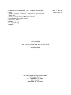
7 The antenna board located on the chassis is used for FM antennas and is shipped with the built-in antenna connected to the screw type terminal. If an external FM antenna is used the built-in antenna lead must be dis connected and the lead-in from the external antenna connected to these terminals. Use only 300 ohm antenna lead-in wire for this purpose. (See illustration on page 2.) If an outside AM antenna is used, connect the lead-in wire to the extra connector furnished on the antenna board. Do not disconnect the leads from the built-in AM antenna . (See illustration on page 2.) This receiver does not require a ground connection. PAGE 3 OPERATION ~~-------------------------------------- --------------~/ PHO ON-OFF SWITCH AND VOLUME CONTROL TONE CONTROL STATION SELECTOR DIAL TONE TUNING AM FM ON -OFF a VOLUME FUNCTION SWITCH Turning will be this knob to the right switches the receiver on.
8 The receiver in operating condition after approximately 30 seconds necessary for warming up. Turning this knob to the left decreases the volume; to the right increases the volume. The knob setting should be advanced when searching for stations and then reduced to facilitate accurate tuning after the station has been picked up. When the station has been tuned in properly, the volume control knob should be turned to the point giving the desired volume. Never attempt to reduce the volume by detuning the station with the sta tion seiector knob. Always use the volume control knob. Rotation of the knob to the right modifies the tone, emphasizing the bass notes.
9 Rotation of the knob to the left emphasizes the high or treble notes. Using the dial pointer as a guide, tune in the desired station by turning the knob until the program has the deepest tone and least amount of back ground noise. If the frequency of a desired station is known and you are within its range, it can be tuned in within a degree or two of its corresponding dial marking. See "What to Expect From Frequency Modulation" on page 5 of this leaflet. The frequency of broadcasting stations can be usually found in the Radio program page of your local newspaper or in a " Radio log." Standard Broadcast (AM): The lower scale on the dial is read when tuning stations on this band.
10 It is marked in kilocycles (KC) and actual fre quency (in kilocycles) may be read by adding a zero (0) to any number shown on this scale. Frequency Modulation Band (FM): The upper scale on the dial is read when tuning stations on this band. It is marked in megacycles (MC) . and the frequency (in megacycles) of the stations may be read directly on this scale. PAGE 4 FUNCTION SWITCH WHAT TO EXPECT FROM FREQUENCY MODULATION Turn the knob to the desired position as indicated by the engraved pointer. FM - When the !mob is turned to "FM", frequency modulated stations can be tuned in. AM -When the knob is turned to "AM", standard broadcast stations can be tuned in.