Transcription of Simple Multi-Band Vertical Dipole - DJ0IP
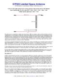
1 Simple multi band HF Vertical Dipole By DJ0IP , November 2014 Page 1 Simple multi band HF Vertical Dipole By DJ0IP , November 2014 Page 2 DESCRIPTION: This Simple non resonant Vertical Dipole enables users with limited space to erect an antenna capable of being used on all ham bands from 80 through 10m. It requires NO RADIALS. Yet its performance is amazing for its size and simplicity. This antenna requires a GOOD antenna matchbox with much broader impedance matching capability than the ATU s built into most transceivers. The ideal matchbox will be a balanced (symmetrical) matchbox.
2 There are very few of these currently available on the market. You may substitute an asymmetrical matchbox with external balun, but care should be taken in the choice of matchbox and balun. More antenna Matchbox and Balun details are shown at the end of this paper. If your matchbox has a built in balun, you may try it but don t be surprised if you encounter problems. Most matchbox manufacturers use the wrong type of balun in their products. For more information, see: PHYSICAL DESCRIPTION: Height: 12m (40 ft.) Wire Length: 6m (20 ft.) per side; 12m (40 ft.)
3 Total Guy Line Distance: 5 to 8m (17 to 25 ft.) The distance from the pole to the ground stakes may be slightly shorter for the 2 guy ropes but the guy line using the feedline as a guy should be as long as possible. The angle of the feedline to ground should not be less than 45 degrees (more is better). THEORY OF OPERATION: This antenna proves two popular antenna myths wrong : 1. An antenna must be resonant to be efficient. 2. Short antennas are not very efficient. According to Cebik, W4 RNL (SK), if we can find a way to efficiently match an antenna to the transmitter, antennas as much as 1/8 of their standard size can be an efficient radiator.
4 The reality is, short antennas have very low impedances and antenna matchboxes are usually inefficient when matching low impedances. Special attention must be paid to the matchbox. The use of short openwire feedlines keeps feedline loss low. The challenge is to find the right matchbox to enable an efficient match. ALL MATCHBOXES WERE NOT CREATED EQUAL! Simple multi band HF Vertical Dipole By DJ0IP , November 2014 Page 3 FEEDLINE: In a perfect world, the feedline should be run at a 90 degree angle away from the antenna . In most installations, especially portable installations, this is difficult, even impossible.
5 And it is NOT necessary. Always try to keep the feedline as high as possible when routing it away from the antenna , but don t worry at all if you cannot run it at a 90 degree angle! In most installations where we have used this antenna , we have installed it as shown in the picture on the first page, with the feedline sloping down at a 45 degree angle. The antenna will still perform very well, even with the feedline at this angle. FEEDLINE LENGTH: Long ago I was taught (personally) by Lew McCoy, W1 ICP (SK) that the optimum length of the feedline should be: long enough to reach from the antenna s feedpoint to the matchbox in the shack.
6 Theoretically, that is all you need to know, because performance wise there really is no critical length as long as your matchbox is capable of efficiently dealing with the resulting impedance. In practice, we will find that certain feedline lengths will transform the impedance on one or more bands to a value outside of the matching range of the matchbox. Not only will the matchbox fail to match the load, this may also cause arcing inside the matchbox during the tuning process and damage the matchbox. TWO SOLUTIONS: 1) buy a better matchbox; 2) change the feedline length.
7 CAUTION: tables of recommendations for good lengths of openwire feedline were created assuming a resonant Dipole . This antenna does not use a resonant Dipole . It intentionally uses a non resonant Dipole to help avoid extremely high impedances. This makes those tables invalid. The hardest band to match is 80m where the impedance is extremely low. So use W1 ICP s formula: cut the feedline to the length you need it and extend it when necessary. RULE OF THUMB: If you encounter arcing in the matchbox, or a band which will not match, even at low power levels, you should add 1/8 wavelength of feedline to the existing feedline.
8 In fact I have often found that adding just 1/16 wavelength was enough to solve the problem. THE FOLLOWING TABLES OF FEEDLINE EXTENSION LENGTHS show typical 1/8 wavelength lengths for Window Line, such as WIREMAN, and assumes the velocity factor of : MHz M Ft. MHz M Ft. multi band HF Vertical Dipole By DJ0IP , November 2014 Page 4 As stated above, you don t always need this much additional feedline. For instance, for 40m I have always used a 13 ft. long piece of feedline, and it has always worked for me. These are approximate lengths and good starting points.
9 CAUTION: NEVER TUNE AN antenna MATCHBOX WITH FULL POWER! Always reduce power to about 10 to 20 watts while tuning the matchbox. After you are certain that the SWR is good, increase the power level. CAUTION: NEVER ROTATE A MATCHBOX SWITCH UNDER POWER! Roller inductors are designed to be adjustable under power. Switched inductors are not! Matchboxes with switched inductors: MUST NOT BE ADJUSTED WITH POWER APPLIED TO THE MATCHBOX! If you need to rotate the switch, un key the transmitter to remove power, rotate the switch, then key the transmitter again.
10 NOTE: The matchbox recommended here (MFJ 974B) is a switched inductor matchbox! CONSTRUCTION TIPS: DO NOT USE THICK WIRE when mounting this antenna to telescoping fiberglass poles. Thicker wire near the top of the pole may result in breakage of the pole. The wire recommended in the drawing (CQ 532) is AWG 18 wire. Make the feedpoint insulator as lightweight as possible. It does not have to support much weight and there is very little force on it. Insulators are NOT necessary on the ends of the wires. Tie a Simple knot near the end of each wire to prevent it from slipping after it has been fastened to the pole.