Transcription of SIMPLER TO SERVICE - OEM Dynamics
1 PUMP DRIVES. next generation DYNAGEAR. HYDRAULIC PUMP DRIVES AUSTRALIA. FEATURING. MODULAR DESIGN. SIMPLER TO SERVICE . DYNAGEAR. WET SPLINE. DROP-IN REPLACEMENT. WITH OTHER BRANDS. QUIETER OPERATION. COMPETITIVE PRICING. CLASS 10 GEARS. NEW. FEATURES and BENEFITS. NEW. MODULAR DESIGN bearings and gears are self-contained within the housings. Input and output adaptors are not required to retain the bearings. Input and output adaptors can be added or changed anytime prior to unit installation. SOS SPUR GEARS (solid-on-shaft) one-piece gear/shaft design provides consistent and uniform alignment. Reduces the total number of parts. Bearings pressed on gears simplify assembly. SIMPLER TO SERVICE does not require pressing shafts into bearings and gears through the housings. Ball bearings do not require shimming or special adjustment of pump pads and input adapters. FEWER PARTS adapter groups are reduced to a single set of input housings and output pads for the entire product line.
2 Gears (31 total) are interchangeable across different models. WET SPLINE oil passages built into the housings, along with the bearing design, create constant oil flow across splines and through bearings, resulting in longer, trouble-free operation. DROP-IN REPLACEMENT footprint is interchangeable with present pump drives and with the competition. HIGHER RATING gear geometry and large ball bearings result in a higher horsepower rating over the present product line. QUIETER OPERATION AGMA class10 gears provide smoother operation. COMPETITIVE PRICING due to economy of scale; commonality of parts results in higher volume of fewer parts. Gear and housing designs result in less assembly time. SHORT LEAD TIME large inventory range held in Australia allows quick turn around of orders. HYDRAULIC PUMP DRIVES RATINGS. Durst has developed a family of gear drive products for The power ratings in this brochure are based upon the following use with hydraulic pumps and motors.
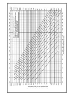
3 These drives are operating conditions: available for mounting SAE standard hydraulic flanges Continuous SERVICE (8 hours/day). and pump or motor shaft configurations directly to the Uniform operating loads. gear drive unit. Models are available to mount directly to Maximum oil sump temperature of 93 C (200 F). SAE flywheel housings, with or without clutches or can be driven through independent mounting arrangements. Ratings are based upon component life using a 1:1 ratio @ 2500. rpm for a 2000 hour L-10 life. The full unit rating can be loaded THERMAL CAPACITY through one pump pad provided the total loading does not exceed The thermal capacity is defined as the power a gear drive unit rating. Durst pump drives are engineered for an optimum will transmit continuously without overheating. Durst pump balance between mechanical and thermal capacities. Durst drives drives are used in such a wide variety of operating are designed to accept 100 percent starting overloads or momentary conditions that only mechanical ratings are shown.
4 Under peaks from electric motor driven applications. conditions such as restricted air circulation, high speeds and high loads, the thermal capacity may be less than RPM LIMITATIONS. the mechanical rating. Checking the thermal capacity is For shaft speeds in excess of 3000 rpm consult factory. extremely important during the first few hours of operation. If the heat is being generated faster than it can be ENGINE HOUSING ADAPTORS. dissipated, severe damage may result and provisions for Housing adaptors SAE 1, 2, 3 & 4 are available for all models. additional cooling should be provided. This may be accomplished by air circulation around the unit or by a HYDRAULIC PUMP ADAPTORS. recirculating oil system (see below). If additional cooling Pump rotation is anti-enginewise. Standard available pump adaptors is not possible a larger capacity unit should be used. and sleeves include SAE A, B, C, D & E.
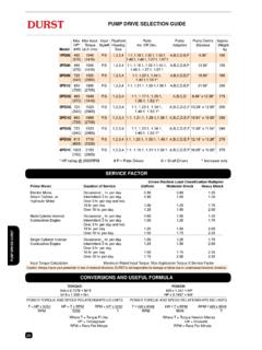
5 OPTIONAL LUBE PUMP AND OIL COOLER. REDUCED PUMP SPLINE WEAR. Most models can be supplied with a centrally mounted All Durst models now feature a new lubrication system where the gear pump for passing lube oil to a water or air cooled lubricant is directed through the centre of the gear to the gear shafts heat exchanger. We stock heat exchanger kits for most across the pump spline intersections. This feature ensures that models. premature spline wear caused by fretting will not occur. OIL OUT BACK TO. OIL IN FROM GEARBOX THROUGH. GEARBOX COOLER. OPTIONAL LUBE PUMP. HYDRAULIC PUMP DRIVES. PUMP DRIVE QUICK SELECTION GUIDE. Max. Max Input Input Flywheel Ratio Pump Pump Centre Approx. HP* Torque Style# Housing Inc. OR Dec. Adaptors Distance Weight Model (kW) (nm) Size kg 495 1040 1:1, :1, :1, :1, 1PD06 P,S 1,2,3,4 A,B,C,D,E,F " 100. (370) (1410) :1, :1, :1, :1. 495 1040 1:1, :1, :1, :1, 2PD06 P,S 1,2,3,4 A,B,C,D,E,F " 135.
6 (370) (1410) :1, :1, :1. 725 1523 1:1, :1, :1, 2PD08 P,S 1,2,3,4 A,B,C,D,E,F " 160. (540) (2065) :1, :1^. 950 1995 1:1, :1, :1, :1. 2PD10 P,S 1,2,3,4 A,B,C,D,E,F " 230. (708) (2705). 495 1040 1:1, :1, :1, 3PD06 P,S 1,2,3,4 A,B,C,D " x " 175. (370) (1410) :1, :1^. 725 1523 1:1, :1, :1, 3PD08 P,S 1,2,3,4 A,B,C,D,E,F " x " 200. (540) (2065) :1, :1^. 950 1995. 3PD10 P,S 1,2,3,4 1:1, :1, :1, :1 A,B,C,D,E,F " x " 295. (708) (2705). 725 1523 1:1, :1, :1, 4PD08 P,S 1,2,3,4 A,B,C,D,E,F " x " 240. (540) (2065) :1, :1^. 1025 2153. 4PD11 P,S 1,2,3,4 1:1, :1, :1, :1 A,B,C,D,E,F " x " 375. (765) (2920). * HP rating @ 2500 RPM # P = Plate Driven S = Shaft Driven ^ Increaser only SERVICE FACTOR. Driven Machine Load Classification Multiplier Prime Mover Duration of SERVICE Uniform Moderate Shock Heavy Shock Electric Motor, Occasional _ hr. per day Steam Turbine, or Intermittent 3 hr.
7 Per day Hydraulic Motor Over 3 hr. per day and incl. 10 hr. per day Over 10 hr. per day Multi-Cylinder Internal Occasional _ hr. per day Combustion Engine Intermittent 3 hr. per day Over 3 hr. per day and incl. 10 hr. per day Over 10 hr. per day Single Cylinder Internal Occasional _ hr. per day Combustion Engine Intermittent 3 hr. per day Over 3 hr. per day 10 hr. per day Over 10 hr. per day Input Torque Calculation Maximum Rated Input Torque Max Application Torque X SERVICE Factor Caution: Always insure your powertrain is free of torsional vibrations. DURST is not responsible for damage or failure due to unaddressed torsional vibrations CONVERSIONS AND USEFUL FORMULA. TORQUE POWER. Nm x = lbf ft kW x = HP. lbf ft x = Nm HP x = kW. POWER TORQUE AND SPEED RELATIONSHIPS US UNITS POWER TORQUE AND SPEED RELATIONSHIPS ISO UNITS. T = HP x 5252 HP = T x RPM RPM = HP x 5252 T = kW x 9549 kW = T x RPM RPM = kW x 9549.
8 RPM 5252 T RPM 9549 T. Where T = Torque Ft Lbs Where T = Torque Newton Metres HP = Horsepower kW = Kilowatts RPM = Revs Per Minute RPM = Revs Per Minute DIMENSIONS. MODEL 1PD 5/8-11 UNC X DEEP. 2 PLACES BOTH SIDES. *. * Pads SAE D2 and E = " F = ". MODEL 2PD A D. 2PD06 2PD08 2PD10. A " " ". B " " " H. C " " " H. B J J. D " " ". E* " " ". H " " ". J " " ". K " " " 5/8-11 UNC X DEEP. 4 PLACES BOTH SIDES. 3/4-10 UNC X DEEP 4 PLACES. L " " " C C L K BOTH SIDES L K. E* 2PD10. * Pads SAE D2 and E = " F = " 2PD06 and 2PD08. MODEL 3PD A/2. A. D H. J. 3PD06 3PD08 3PD10 5/8-11 UNC x 1". A " " " DEEP 4 PLACES. BOTH SIDES. B " " ". C " " ". D " " " L K. E* " " " B C 3PD08. F " " " J. G " " ". G. H 0 " 0. J " " " B/2. J. K " " ". L " " ". 5/8-11 UNC x 1" DEEP. 4 PLACES. BOTH SIDES L K. * Pads SAE D2 and E = " F F. E* 3/4-10 UNC X F = " 3PD06. DEEP 4 PLACES. BOTH SIDES. L K.
9 3PD10. MODEL 4PD A. A/2. D. C. 4PD08 4PD11. A " ". B " ". C " ". D " ". E* " " G. F " " B. H. J. G " ". H " " G. J " ". B/2. K " " 4PD08. 5/8-11 UNC x 1" DEEP. L " " 4 PLACES. BOTH SIDES. 4PD11. * Pads SAE D2 and E = " 3/4-10 UNC X DEEP. F = " F F. 4 PLACES BOTH SIDES. L K. E. INPUT and OUTPUT OPTIONS. FLYWHEEL and HOUSING ADAPTORS. SAE Flywheel Housing Options SAE No. A B. 1 " ". 2 " ". 3 " ". 4 " ". SAE Drive Plate Options A BC D. SAE No. C D G. 8 " " ". 10 " " ". 11 1/2 " " ". 14 " " ". G " " * " Varies with drive size * D2, E and F Pads are thicker Fixed Driveplate Flexilock TV Rubber Block TV. Caution: Always insure your powertrain is free of torsional vibrations. DURST is not responsible for damage or resistant drive resistant drive failure due to unaddressed torsional vibrations SAE PUMP and SHAFT ADAPTORS. K. M Dia. SAE Pump Adapter Plates SAE Shaft Adapters Mounting Splined 2 Bolt type 4 Bolt Type B Dia.
10 Flange Shaft Size K M B S R SAE Teeth & Pitch A " " " - - A 9T - 16/32. B " " " " " B 13T - 16/32. C " " " " " BB 15T - 16/32 R Dia. D " " " " " C 14T - 12/24. E " " " " " CC 17T - 12/24. F " " " " " D 13T - 8/16. E 13T - 8/16. F 15T - 8/16. - 21T - 16/32 S. - 23T - 16/32. - 27T - 16/32. INPUT SHAFT / FLANGE OPTIONS. 29T - 12/24. 1/2" Spline Keyway ". ". 65mm ". ". ". " " " 19mm ". " " " ". Companion Flange Companion Flange " Straight shaft 65mm Straight shaft 29 Tooth 12/24. Spicer 1610 series Spicer 1810 series with 1/2" key with no key Splined shaft Other Shaft Option Available. Specials Made To Order. OTHER POWER TRANSMISSION PRODUCTS. Flexible Couplings for Hydraulics Splined Components for Hydraulic Motor Disconnect With Clamplock Spline Locking Hydraulics and Mobile Equipment DYNAGEAR. AUSTRALIA. DYNAGEAR. AUSTRALIA. Hydraulic Motor Overhung Load Adaptors Single Pump Drives for Diesel Engines FLEXILOCK.