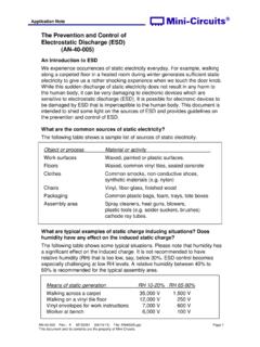
Transcription of Simulating Electrostatic Discharge - JDS
1 6 Simulating Electrostatic Discharge Dejan Maksimovi , Guido Notermans Abstract - In this paper we justify the necessity of the Electrostatic Discharge simulation. We give an overview of the ESD stress standards and the ESD protection devices. We further describe the modelling of the ESD devices and give a case study which shows the importance of timely ESD simulation for the design success. Keywords ESD, simulation, modelling, HBM, MM, CDM, HMM. I. INTRODUCTION Electrostatic Discharge (ESD) occurs between two bodies at different Electrostatic potentials. The charging of these bodies can occur either by triboelectricity or by induction.
2 ESD is characterized by a short duration ( to 100ns), high current (1A to 30A) pulse. Such high current can damage the semiconductor device. Failures can be thermally induced due to the high power dissipated during the ESD event: silicon melting can be observed as well as metal or polysilicon resistance blow-up if the metal/poly line is not designed wide enough. Gate oxide breakdown can also be observed due to the large voltage drop bult-up by the ESD current. ESD can occur any time in the life of the product: during manufacturing, assembly, testing, shipment and in the final application and it is a key issue for the reliability of the integrated circuits (ICs).
3 Two approaches are used together to fight against the ESD. The first one is to prevent the ESD events. Special dissipative materials are used in clean rooms and labs, ionizers, proper grounding of the equipment, wearing of a wrist strap during the tests etc. The second approach is to implement efficient ESD protection on the IC. The ideal ESD protection circuit is similar to a switch: it is highly resistive during the normal operation of the IC, but it is able to detect an ESD event and to become low resistive when it occurs. In such a way the ESD device shunts the ESD current with the lowest possible voltage drop.
4 II. MODELING THE ESD EVENTS There are many ESD models, three of them being the most widely used: human body model (HBM), machine model (MM) and charged device model (CDM). 2A. human body model (HBM) This model corresponds to the Discharge of a charged human being into the IC. The capacitance of the average human body (to ground) is 100pF. The average skin resistance is The body capacitance is charged to a certain voltage level and discharged throuth the skin resistance and the device under test (DUT) to the ground. The electronic circuit representing this event is shown in Figure. Fig. human body model (HBM).
5 This ESD model is defined by the JEDEC standard JESD22-A114F [1]. 2B. Machine model (MM) This model emulates the Discharge that can occur in automatic assembly lines between a machine and the IC. The charged machine has a higher capacitance of 200pF, while the contact resistance is very low, almost zero, often considered as a few ohms. Due to the low resistance, this model is strongly dependent on the parasitic inductance which has to be fixed and is in the order of The electronic circuit representing this kind of ESD event is shown in Figure. Dejan Maksimovi and Guido Notermans are with the ST-Ericsson, Binzstrasse 44, 8045 Zurich, Switzerland, E-mail.
6 Proceedings of Small Systems Simulation Symposium 2010, Ni , Serbia, 12-14 February 2010 7 :0 Fig. Machine model (MM). This ESD model is defined by the IEA/JEDEC standard IEA/JESD22-A115-A [2]. 2C. Charged Device model (CDM) This model emulates the Discharge of a charged IC to the ground which occurs when one pin of the IC touches a grounded surface. The whole IC is charged and the Discharge is determined by many device parameters such as the package type and the die size. The CDM event is very short (rise time is less than ) high current pulse in order of tens of amperes. It mostly causes the gate oxide failures due to the overvoltage caused by such a high current.
7 A typical CDM current waveform is shown in Figure Fig. Charged Device model (CDM). During the CDM test the device is placed in a "dead bug" position on a charging plane connected to a high voltage source. Above the device there is a ground plane. The Discharge occurs when the pogo pin connected to the ground plane touches one pin of the IC. This ESD model is defined by the JEDEC standard JESD22-C101C [3]. While the HBM and MM events occur between two pins of the IC and the circuit can be designed in such a way that the ESD current path is predictable, during the CDM stress the current comes from the silicon substrate and distributes in an unpredictable way through the metal lines and devices towards the stressed pin.
8 2D. System Level ESD Stress (Gun Test) This model corresponds to the "real-world" Discharge that happens when the final user handles the product that contains the IC. The stress levels are much higher and the test is performed using the ESD gun. The Discharge is applied to every possible exposed surface of the product, such as metal connectors, displays, case, etc. The ESD current flows from the stressed point to the system ground (and another way around), which is similar to the CDM Discharge . The current waveform is shown in Fig. It consists of a very short CDM-like first pulse of very high amplitude and a HBM-like second pulse of the amplitude higher than that of the HBM pulse for the same stress level.
9 The gun pulse parameters for different stress levels are given in Table Fig. Gun test current waveform. TABLE GUN TEST CURRENT WAVEFORM PARAMETERS FOR DIFFERENT STRESS LEVELS TABLE HBM PEAK CURRENT VERSUS THE FIRST PEAK AMPLITUDE IN THE GUN TEST Applied voltage [kV] HBM peak current [A] Gun test first peak current [A] 2 4 6 8 10 This ESD model is defined by the IEC standard 61000-4-2 [4].
10 Table compares the maximum peak current during the HBM and gun test for the same voltage levels [5]. 2E. Transmission Line Pulse (TLP) Measurement The ESD tests described so far are pass/fail measurements. They do not give any information on the behaviour of the IC during the ESD event. To obtain I(V) characteristics of the ESD protection circuits and devices a special tool called TLP is used [6]. During the TLP measurement, the DUT is subjected to a trapezoidal positive current pulse. Once the transients in Proceedings of Small Systems Simulation Symposium 2010, Ni , Serbia, 12-14 February 2010 8 the device are over, the current through and the voltage over the DUT are measured.