Transcription of Simulation of ammonia synthesis - Science …
1 American Journal of Chemical Engineering 2013; 1(3): 59-64 Published online November 30, 2013 ( ) doi: Simulation of ammonia synthesis M. R. Amin, S. Sharear, N. Siddique, Shaidul Islam Chemical Engineering Department, BUET, Dhaka, Bangladesh Email address: (M. R. Amin) To cite this article: M. R. Amin, S. Sharear, N. Siddique, Shaidul Islam. Simulation of ammonia synthesis . American Journal of Chemical Engineering. Vol. 1, No. 3, 2013, pp. 59-64. doi: Abstract: ammonia is prodeuced to give a final product named urea which is a very important fertilizer for higher nitrogen processes has been invented for optimum production of ammonia . Now-a-days, ammonia production is mainly done by Haber process in which nitrogen andhydrogen react in the presence of an iron catalyst to form ammonia . The hydrogen is formedby reacting natural gas and steam at high temperatures and the nitrogen is supplied from theair.
2 Other gases (such as water and carbon dioxide) are removed from the gas stream andthe nitrogen and hydrogen passed over an iron catalyst at high temperature and pressure toform the ammonia . In our work, Simulation of ammonia synthesis process is done on Aspen Hysys By using +005kmole/hr methane, +005kmole/hr hydrogen, +005kmole/hr nitrogen, we +004 kmole/hr has also been found that ammonia production increases with the rise of pressure of fresh feed. Keywords: ammonia , Simulation , Heber, Fertilizer, Reformer 1. Introduction ammonia is a compound of nitrogen and hydrogen with the formula NH3. It is a colorless gas with acharacteristic pungent smell. ammonia [1] contributes significantly to the nutritional needs of terrestrial organisms byserving as a precursor to food andfertilizers [5]industry [8]. ammonia , both directly or indirectly, is also a building-block for thesynthesis of many pharmaceuticals and is used in many commercial cleaning products.
3 Although in wide use, ammonia is both caustic and hazardous. Theglobal production of ammonia for 2012 is anticipated to be 198 milliontons, a 35% increase over the estimated 2006 global output of million tones. ammonia , as used commercially, is often called anhydrous [2] ammonia . This term emphasizes the absence of water inthe material. Because NH3 boils at C ( F) at a pressure of 1 atmosphere, the liquid must be storedunder high pressure [3] or at low temperature. "Household ammonia " or "ammonium hydroxide" is a solution of NH3 inwater. The concentration of such solutions is measured in units of the Baum scale (density), with 26 degreesBaum (about 30% w/w ammonia at C) being the typical high-concentration commercial product. Householdammonia ranges in concentration from 5 to 10 weight percent ammonia . In this experiment a detailed study is performed about the process by means of Simulation in Aspen [11].
4 Since Haber process is widely used for maximum production of ammonia , we have simulated the process that is based on Haber [10] process. Though Simulation does not give the real world performance or the real life production environment but if the basic process is known and related data are available, it surely is the best way by which an individual can get ideas of an industrial process without conducting any experiment. 2. Methodology The process of producing ammonia is simulated in Simulation software Aspen Aspen HYSYS process simulator is a core element of AspenTech sAspenONE engineering applications. It provides quite accurate results which makes it an efficient simulator. It provides comprehensive thermodynamics basis for accurate determination of physical properties, transport properties, and phase behavior. Aspen HYSYS can be used to determine outlet process conditions if the inlet conditions like temperature, pressure, and composition are specified.
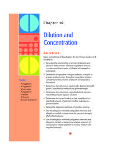
5 In this Simulation we used Peng-Robinson model fits best to equilibrium process. 60 M. R. Amin et al.: Simulation of ammonia synthesis Process Description The simplified block diagram ofammonia synthesis is given below. Figure 01. block diagram of ammonia synthesis . Figure 02. Hysys Process flow diagram of ammonia synthesis . Reaction Involved In hydrogen production step, four reactions are are- ZnO + H2S= ZnS + H2O this reaction is done to carried out all sulpher compounds from natural gas. Following reactions occur in reformer- CH4 + H2O = 3H2 + CO CH4 + 2H2O = 4H2 + CO2 CO + H2O = H2 + CO2 This gaseous mixture is known as synthesis gas. In nitrogen addition step, synthesis gases are mixed with air in the secondary reformer. The reactions are- CO + H2O = CO2 + H2 American Journal of Chemical Engineering 2013; 1(3): 59-64 61 O2 + 2CH4= 2CO + 4H2 O2 + CH4 =CO2 + 2H2 2O2 + CH4= 2H2O + CO2 In carbon monoxide removal step, carbon monoxide is removed by water gas shift reaction.
6 CO + H2O= CO2 + H2 In Removal of carbon oxides step, all carbon oxides are converted to methane by following reactions- CO + 3H2= CH4 + H2O CO2 + 4H2= CH4 + 2H2O In ammonia synthesis step, fowlloing reaction provides final product ammonia - N2 + 3H2= 2NH3 Hydrogen Production Hydrogen is produced by the reaction of methane with water. However, before this can becarried out, all sulfurous compounds must be removed from the natural gas to preventcatalyst [4] poisoning. These are removed by heating the gas to 400 oC and reacting it with zincoxide. Following this, the gas is sent to the primary reformer for steam reforming, where super-heated steam is fed into the reformer with the methane. The gas mixture heated with naturalgas and purge gas to 770oC in the presence of nickel catalyst. At this, methane converts to hydrogen,carbon dioxide and small quantities of carbon monoxide.
7 Nitrogen Addition The synthesis gas is cooled slightly to 7350C. It then flows to the secondary reformer whereit is mixed with a calculated amount of air. The highly exothermic reaction between oxygenand methane produces more hydrogen. In addition, the necessary nitrogen [6] is added in the secondary the catalyst that is used to form the ammonia is pure iron, water, carbon dioxide andcarbon monoxide must be removed from the gas stream to prevent oxidation of the iron. Thisis carried out in the next three steps. Removal of Carbon Monoxide Here the carbon monoxide is converted to carbon dioxide (which is used later in the synthesisof urea) in a reaction known as the water gas shift is achieved in two steps. Firstly, the gas stream is passed over a Cr/Fe3O4catalyst [9] at3600C and then over a Cu/ZnO/Cr catalyst at 2100C. The same reaction occurs in both steps,but using the two steps maximizes conversion.
8 Water Removal The gas mixture is further cooled to 400C, at which temperature the water condenses out andis removed. Removal of Carbon Oxides The gases are then pumped up through a counter-current of UCARSOL solution (aMDEA solution). Carbon dioxide is highly soluble in UCARSOL, and more than of the CO2in the mixture dissolves in it. The remaining CO2 (as well as any CO thatwas not converted to CO2 in Step 3) is converted to methane (methanation) using a Ni/Al2O3catalyst at 3250C. The water which is produced in these reactions is removed by condensation at 400C as carbon dioxide is stripped from the UCARSOL and used in urea manufacture. TheUCARSOL is cooled and reused for carbon dioxide removal. synthesis of ammonia The gas mixture is now cooled, compressed and fed into the ammonia synthesis loop. A mixture of ammonia and unreacted gases which have already been around theloop are mixed with the incoming gas stream and cooled to 50C.
9 The ammonia present isremoved and the unreacted gases heated to 4000C at a pressure of 330barg and passed overan iron catalyst. Under these conditions 26% of the hydrogen and nitrogen are converted toammonia. The outlet gas from the ammonia converter is cooled from 2200C to 300C. Thiscooling process condenses more the half of the ammonia , which is then separated remaining gas is mixed with more cooled, compressed incoming gas. The reactionoccurs in the ammonia ammonia is rapidly decompressed to 24barg. At this pressure, impurities such asmethane and hydrogen become gases. The gas mixture above the liquid ammonia (whichalso contains significant levels of ammonia ) is removed and sent to the ammonia recoveryunit. This is an absorber-stripper system using water as solvent. The remaining gas (purgegas) is used as fuel for the heating of the primary reformer.
10 The pure ammonia remaining ismixed with the pure ammonia from the initial condensation above and is ready for use in ureaproduction, for storage or for direct sale. 3. Results and Discussions By using +005kmole/hr methane, +005kmole/hr hydrogen, +005kmole/hr nitrogen we have +004kmole/hr ammonia . From graph we can see that ammonia production increases with the rise of pressure of fresh feed. From figure-03, it has been seen that with increase of pressure of resh feed tube side delta T decreases gradually to at +004 kPa. After reaching this value delta T increases at high rate. From figure -04, in the case of tube side delta T(0C),delta T increases to 0C in a linear fashion with positive slope with respect to fresh feed temperature. On the other hand, in the case of shell side delta T(0C),delta T decreases in a linear fashion with negative slope.