Transcription of Simulation of Spacecraft Attitude and Orbit …
1 Simulation of Spacecraft Attitude and Orbit dynamics Pasi Riihim ki, Jean-Peter Yl n Control Engineering Laboratory Helsinki University of Technology PL-5500, 02015 TKK E-mail: KEYWORDSS imulation Model, Satellite, FDIR, Quaternion ABSTRACTIn this paper, the Simulation model of satellite Attitude and Orbit dynamics is discussed. The satellite Attitude model has been represented in term of a quaternion and a ordinary differential equation is used to describe the satellite orbital motion. The different actuators and sensors have been modeled with suitable faults and failures. The Simulation model enables us to consider the satellite motion under different environmental perturbations (for example aerodynamic drag, external celestial body etc.) and failure in actuators and sensors. The Simulation model is utilized in the development of Attitude and Orbit control algorithms or fault detection, isolation and recovery (FDIR) technologies.
2 Simulation results are also given. INTRODUCTIOND uring the last decades modeling, Simulation , and wider computational science and engineering have become more and more important tools in the research and development projects. The design phase has to be reduced in time and cost when the use of new ideas and tools becomes possible. This is also the trend in space application in which the real tests are not possible or at least they are expensive. New demands on the aerospace and control engineering have become up and they have to be able to answer to requirements. Spacecraft simulators or simulators in general, are software tools that can be used by researchers, engineers, students or everybody to analyze and assess system operations, behaviors, and to answer to the questions regarding phenomenon or product.
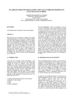
3 The simulations are essential tools in the mission and Spacecraft control design. For example, the scientific missions are unique and the instrumentation of a Spacecraft is designed only for this specific mission. There are not any ready-to-use platforms that can be used. Hence, it is not possible to verify the operation of control algorithms and strategies in real process but the Simulation environments can be are plenty of companies that offer their Simulation services to the research institutes and space companies. MODEL STRUCTURE AND MATHEMATICS Model Structure The Spacecraft Simulation model is organized like any actual control loops (See Figures 1.). The interfaces of the components are defined and modeled in such a way that the Simulation model would be as modular as possible.
4 Modifications to the Simulation model are easy to do and one part of the model can be easily replaced with another. The model is initialized and controlled from the coordination level. This means that the model parameters and possible faults and failures in the FDIR Simulation case are defined. Figures 1. Spacecraft Simulation model structure. Coordinate Systems Three different coordinate systems are defined in the Coordinate System (ICS), Coordinate System (OCS), and Coordinate System (BCS). The inertial coordinate system is usually defined such that the center of mass of the Earth (cm) acts as origin and the direction of the axes are fixed to the solar system. This kind of coordinate system is not exactly inertial but it is enough for all engineering purposes (Sidi 1997).
5 The Z-axis of the ICS is the rotation axis of the Earth in a positive direction and the X-Y plane is the equatorial plane of the Earth, which is perpendicular to the Earth s rotation axis. The vernal equinox vector is selected to be the X-axis of the ICS. Finally, the Y-axishas been chosen in such a way that the ICS is right-handed orthogonal coordinate system. Orbit coordinate system is also a right-handed orthogonal coordinate system with origin in the center of the satellite mass. The Z-axis is pointing towards the center of the Earth; X-axis to the direction of satellite perpendicular to the Z-axis, and Y-axis completes the coordinate system such that it is right-handed and orthogonal. The third coordinate system, which has been fixed to the moving and rotating Spacecraft , defines satellite orientation.
6 RotationThe Attitude transformation in space can be executed by using various different aspects. In the Simulation model, the quaternion technique is used. The main feature of quaternions is that they provide a convenient product rule for successive rotations and they have simple form of kinematics (Wertz 1978, Wis niewski 1996).The basic definition of the quaternion is a consequence of the property of the direction cosine matrix Athat it has at least one eigenvalue of unity. This means that there is an eigenvector e (Euler axis) that is unchanged in every rotation. The quaternion is defined as a vector (1) where qi R,i,j and k satisfy the Hamilton s rule (2) and where the length of the quaternion is unity. (Sidi 1997)41 2 3qq q q=++ +qijk (1) 22 21== = = = == == =ijkijkijjikjkkj ikiikj (2) When the Euler axis e of the rotation is known the connection between quaternion and the rotation Euler axis is ()()()()1122334sin2sin2sin2cos2qeqeqeq = = = = whereeiis a component of Euler axis and is the magnitude of the rotation.
7 The final combined rotation of two successive rotations can be performed as a matrix-vector multiplication (3) whereq and q are the individual rotations. '' ''143 21'' ''234 12''''32143'' ''41234'''qqq qqqqq qqqqqqqqqq qq == qqq (3) Simulation MODEL The Simulation model is realized in the MATLAB/ Model The motion of a celestial body is based on the quite elementary principles of celestial mechanics. In the 17thcentury, J. Kepler provided three basic empirical laws that describe the motion of planet in unperturbed planetary Orbit . The orbital dynamics of a satellite is extensively explained in many books, for example (Sidi 1997) and (Wertz 1978). If we consider a system of two particles P1 and P2 of massesm1 and m2 and apply Newton s second law and the law of gravity to the two-body system, we can get the fundamental equation (4) of the motion of the two-body system where the symbol =G(m1+m2) and G is the universal constant of gravitation.
8 This equation describes the motion of the particle P1 relative to the second mass +=rr (4) In general, if a particle P moves in a force field F, the momentum of the force F about origin OisM=r Fwherer is the position vector of the particle P. The angular momentum about origin is h=m(r v)= r pwherep is the linear momentum of the particle. Thus, the time rate of the angular momentum h is equal to the moment of the force F.()0ddmdtdt= =+ =hrvrFM (5) The equation (5) states the fundamental fact that the momentum acting on a particle is equal to the time rate of the change of its angular momentum. In space science it is common to describe the satellite Orbit by five numbers, known as orbital elements or classical orbital elements (COE).
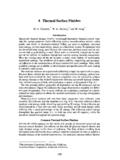
9 A sixth element is added to determine the location of the satellite in its Orbit (Wertz 1978 and Sidi 1997). The classical orbital elements have been described in the Table 1. Because these elements are poorly defined if e and/or i is equal to zero, so-called equinoctial orbital elements (EOE) have been defined in terms of the classical orbital elements. The equinoctial orbital elements have been defined in Table 2. Table 1. The classical orbital elements. (Sidi 1997) Symbol aei Mthe semi major axis the eccentricity the inclination the right ascension of the ascending node the argument of perigee the mean anomaly Figures 2. The definitions of the 2. The definitions of the equinoctial orbital elements (EOE).
10 (We and Roithmayr, 2001) EOE1212aPPQQl()()()()sincostansin2tancos 2aeeiiM + + + +In Keplerian Orbit the derivative of the first five orbital elements are equal to zero. If the satellite orbital elements are known the satellite location r and the velocity vector v can be calculated, and vise versa. Algorithms to do this can be found in any textbook concerning orbital dynamics , for example (Sidi 1997), (Wertz 1978). In the general case, in which any kind of perturbing force can exist, the equation of orbital motion is 3pr +=rrf with initial condition and where fp is the perturbing force per unit mass. Due to the perturbing acceleration the orbital elements are not constants. Hence, so-called Gauss form of Lagrange s planetary equations describes the derivative of classical orbital elements when the perturbing force is conservative or non-conservative.