Transcription of Single and three-phase shunt reactors loss measurement
1 Single and three-phase shunt reactors loss measurement BORUZ MIRCEA ALEXANDRU, MIRCEA PAUL MIHAI, MIRCEA ION Department of Electrical Engineering, Energetics and Aerospace University of Craiova 107, Blvd. Decebal, Craiova 200440 ROMANIA Abstract: This paper discusses the relations between measurement of loss shunt reactors of five limb design under three-phase and Single phase excitation. Single phase loss measurement , added for all three phases ; give a higher reading than the symmetrical test. The ratio is stable over a wide range of voltage.
2 It is therefore possible to base measurements of losses at rated voltage on Single phase measurement if a correction factor is established by additional three-phase and Single -phase measurements at reduced voltage. Key-Words: loss measurement , correction factor, shunt reactor, Single / three-phase 1 Introduction The test for shunt reactors loss measurement is done by using large capacitors (which are very expensive because of their large number and also for their large maintenance expenses). There might be cases when a testing laboratory can not perform loss measurement for these shunt reactors because they do not have that high number of capacitors.
3 In this paper it will be presented a method for loss measurement by using half of necessary capacitors. For small power shunt reactor loss measurement can be performed by applying three-phase excitation and in this case losses can be measured by using wattmeter on each phase. However there might be cases when these losses can be also determined by Single -phase excitation but in this case there should be calculated a correction factor between Single -phase and three-phase excitation. The IEC 60076-6 / 2007 sub clause says that for loss measurement on Single -phase excitation is possible only with agreement between manufacturer and purchaser.
4 2 loss measurements according to IEC 60076-6 The loss shall be measured at rated voltage and rated frequency. The voltage shall be measured with a voltmeter responsive to the mean value of voltage but scaled the value of a sinusoidal wave having the same value. In exceptional cases, for example large rated power and high system voltage, it may be difficult to meet this test condition. In these cases, the loss at rated voltage shall be obtained by multiplying the measured loss by the square of the ratio of rated current to the current measured at a reduced voltage level [1].
5 For three-phase reactor with a magnetic shield for zero-sequence flux, by special agreement between manufacturer and purchaser, a measurement of loss may be made with Single -phase excitation. In this case, a comparison, at lower voltage, between Single -phase and three-phase measurement must be made and a suitable correction factor agreed [2]. The method for determination of loss is subjected to agreement between purchaser and manufacturer; satisfactory documentation regarding accuracy and reliability of the proposed method shall be provided.
6 As the power factor of a shunt reactor is normally very low, loss measurement using conventional wattmeter methods may be subjected to considerable errors [1]. A bridge method may be used to advantage. A calorimetric method can be used in special cases. The loss in the various parts of the reactor (I2R loss , iron loss and additional loss ) cannot be separated by measurements; it is thus preferable, in order to avoid correction to reference temperature, to perform the measurement when the average temperature of the windings is practically equal to the reference temperature.
7 If this is impracticable, the additional loss as well as the iron loss shall be deemed independent of temperature [1]. If several units are to be tested it is recommended that the unit on which loss measurement is carried out as a type test at approximately reference temperature, shall be measured at ambient temperature also, thus establishing a temperature coefficient for total loss (assuming linear variation). Remaining units will be than measured at ambient Advances in Automatic Control, Modelling & SimulationISBN: 978-1-61804-189-0288temperature only and their loss figure shall be corrected to reference temperature using the temperature coefficient established on the type test unit.
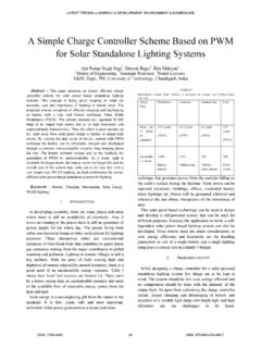
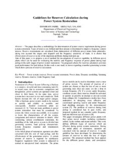
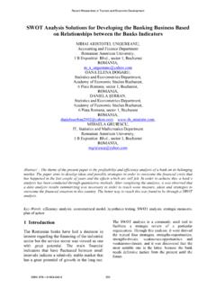
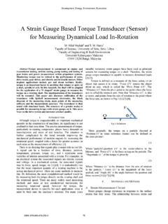
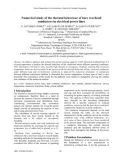
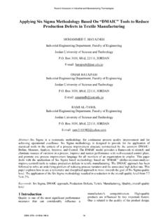
8 If at rated voltage the current measured is different from the rated current the measured loss shall be multiplied by the square of the ratio of rated current to measured current [1]. 3 Power frequency behavior of three-phase shunt reactors under three-phase and Single -phase excitation The reactors are of gapped core design with unwound and non-gapped outer core limbs. The excitation cases to be considered are referred to Single -phase excitation (figures 1 and 2) and three phase excitation (figure 3).
9 Figure 1. Voltage applied on phase U Figure 2. Voltage applied on phase V Figure 3. Voltage applied on phases U, V and W The significance of the outer limbs. The outer limbs give the reactor certain properties: When a Single phase winding is energized, the flux through it finds its return path through the low-reluctance paths of the outer limbs and very little bellow one percent returns through an adjacent gapped core limbs. This can be demonstrated by the corresponding low induced voltage in the adjacent phase winding.
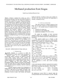
10 In terms of circuit parameters we can express this by saying that the mutual inductance or the coupling factor between phases is low. The phase impedance are practically independent on whether adjacent phases are energized or not. In terms of symmetrical impedance components the zero-sequence or homopolar impedance is very closely equal to the positive-sequence impedance. 4 Anomaly of loss readings under three-phase excitation The equivalent circuit diagram for the complete y-connection reactor is as shown in figure 4.