Transcription of Single / Multistage Restriction FLOW DIVISION …
1 FLOW / Multistage Restriction Orifice s Restriction orifice plate and its assembliesThe Restriction orifices are used for reducing fluid pressure and are designed somewhat different from the orifice plates that are used for measuring flow rates. They are designed to slip between the piping Single Restriction orifices are often sufficient to meet the requirements, there are situations where limitations arise due to process conditions making the Single Restriction orifices unacceptable. In such situations, use of multiple Restriction in series is a better foremost consideration for the case of multiple Restriction is the pressure drop.
2 This applies whether or not the fluid is liquid or vapor/gas. Higher pressure drop implies higher velocities resulting in vibration and noise other consideration is not just about maximum permitted pressure drop and this is particularly for gas flow. If the process condition indicates that critical flow will occur with the use of Single Restriction plate, care should be exercised to avoid operating well beyond the critical pressure drop. Critical implies a pressure drop across the device exceeding 50 percent of the absolute upstream pressure at which point sonic velocity is of Multistage Orifice Assembly comprises of multiple Restriction orifice plates separated by a distance of one pipe diameter and welded with the pipes in between them.
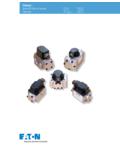
3 End connection is either suitable for butt welding or with end flanges. IBR Form IIIC certificate can be provided as per / Multistage Restrictionorifice assembliesFig Restriction Orifice Assembly10 FLOW DIVISIONG eneral Instruments manufactured Multistage orifice assemblies Where very HIGH pressure DROPS in liquid flows are required are another type of measuring flow with high differential pressure Multistage Restriction ORIFICE ASSEMBLIES may be required meters effectively removing cavitation and flashing conditions. It also to achieve the desired pressure drop whilst preventing problems such helps in killing pressure and thus effectively acting as a pressure as CAVITATION, FLASHING and high NOISE and VIBRATION levels.
4 Reducing element. These are basically used to detect flow of fluids, CAVITATION is a potentially damaging, erosive condition which gasses, steam, steam water, acids, alkalies, crudes, high viscous occurs when the internal pressure of the liquid passing through the fluids, fluids with solid particles, condensation liquids. General make orifice falls below its vapour pressure and vapour bubbles form. of Multistage assemblies lead to a precise measure of differential Further downstream from the orifice the pressure recovers pressure leading to the most precise flow rate taking care of all factors sufficiently to collapse the bubbles with extreme violence.
5 Cavitation of fluid cavitation related to its vapour pressure . The design is calculations are performed during the design stage of a Multistage RO applicable from to 64 of flow measurement. For higher sizes of to calculate cavitation factors at each stage in the orifice and pressure reducing kindly do contact the design and engineering team of General. It is measured at right angles to the flow FLASHING is a similar phenomenon to cavitation except that direction, In a averaging General make Multistage assemblies the the process pressure never recovers sufficiently to collapse the gas kinetic energy of the flowing fluid is transformed into potential energy bubbles resulting in two phase flow - liquid and gas - downstream of for measurement of fluid flow velocity by effectively abrupting to 40% the orifice.
6 Erosion of pipe work and valves and other instrumentation recovery in between two stages and thus, effectively removing the can occur due to the impact of liquid droplets carried at high speed in choking content of the fluid in gas and steam and removing cavitation the vapour flow. in especially liquid state thus essentially reducing industrial noise and CHOKED FLOW IN GASES - also know as critical flow - occurs when restricting to below 80 large a pressure drop is attempted across a Single orifice plate, or Applicationswhen too large flows are forced thru a lesser inlet pipe size.
7 In such cases the flow through the orifice will become sonic, at which point nGas and Liquid Flowsno further increase in flow can be achieved by either increasingnHigh pressure Dropsthe upstream pressure or lowering the downstream pressure . General make Multistage RO will enable staged reductions in pressure to Preventsprevent choked flow and Flashing in Liquid flowsGeneral make Multistage ROs are manufactured from a wide range of nChoked flow in and are engineered to meet specific project process conditions and requirements. Plates are usually welded into pipe with nExcessive Noise / Vibration a separation of one pipe diameter, the number of plates and orifice Restriction orifice plates have traditionally been used to reduce bores being determined by calculation.
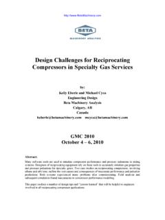
8 Process connections to pressures in GAS AND LIQUID FLOWS by forcing the flow through existing pipe work can be either standard process flanges or a restricted bore. The precise pressure drop is produced by machined ends suitable for butt calculating the orifice bore, having taken into account all the relevant process and flow conditions. / Multistage Restriction Orifice / Multistage Restriction OrificeassembliesStandard as per Miller / ISO5167, AGA-3, , , Series BMultiple Restriction Orifice AssemblyFig