Transcription of SINGLE POINT FLOW CALCULATIONS FOR LIQUEFIED …
1 Page - 1 SINGLE POINT FLOW CALCULATIONS FOR LIQUEFIED compressed GAS fire extinguishing AGENTS by Tom Wysocki Guardian Services, Inc. HISTORY Whether the agent is water, dry chemical, inert gas or a LIQUEFIED compressed gas, engineered system design demands that we deliver a specified quantity of agent to the fire zone in a specified time. The science of hydraulics enables us to predict the flow of substances in networks of pipe and nozzles. Predicting the flow of LIQUEFIED compressed gases used for special fire fighting applications present a unique challenge. The LIQUEFIED compressed gas which has had the longest history of continuous use for fire suppression is carbon dioxide. The NFPA Standard 12 on Carbon Dioxide systems gives a method of calculating flow of CO2 based on the doctoral dissertation of Dr.
2 James Hesson. This same basic methodology was adapted by Mr. Vic Williamson and later refined by the author to predict flow parameters for Halon 1301. In 1977, the Williamson/Hesson two-phase flow methodology was recognized in NFPA 12A, the Standard on Halon 1301 Systems. During the 1970 s and 1980 s, numerous laboratory and countless field tests showed the Williamson/Hesson method of predicting Halon 1301 flow to be sufficiently accurate to design Halon 1301 pipe and nozzle systems. Nonetheless there has been considerable debate over the validity of the approach. As with most every mathematical model of physical reality, there are limits which must be recognized. The approach has been successfully applied to predict flow of Halon 1301, carbon dioxide, HFC227ea, and HFC23. In this paper, we will review the flow theory for LIQUEFIED compressed gases.
3 We will also present the enhancements which must be incorporated in order to use the Williamson/Hesson method for complex pipe networks. FLOW EQUATIONS Bernoulli s equation is a fundamental equation of qualitativestatement of this equation is that the sum of any changes in pressurehead, velocity head, friction head and elevation head in a system is zeroassuming no heat input or loss from the system. In its basic form, this equation can calculate hydraulic parameters for substances whose density is essentially constant with changes in pressure -- in other words, for non-compressible flow. SINGLE POINT FLOW CALCULATIONS Page - 2 ZPvgH++=14422 Figure 1 Bernoulli s Equation Hesson s adaptation of Bernoulli s equation permits CALCULATIONS for substances whose density changes with changing pressure.
4 43 57 + = QfLQDDPP ofof d Both of these equations relating pressure, flow rate, pipe diameter, and pipe length require knowledge of the density of the flowing media as a function of the pressure in the pipe. LIQUEFIED compressed GAS DISCHARGE LIQUEFIED compressed gases exhibit the characteristics of compressible flow. In other words, the density of the agent changes considerably as the pressure in the pipeline decreases. These agents also exhibit two-phase flow in that the flowing agent is comprised of a mixture of liquid and vapor. One of the major problems in predicting pressure drop and flow rate in such a system is deriving an accurate relation between agent density and pressure. Depending on the degree of accuracy needed for the type of fire suppression system, a more or less rigorous approach will be required to calculate the pressure-density relationship.
5 For high pressure carbon dioxide system work, the pressure in the storage container is set to 750 PSI. Density as a function of pressure is calculated by assuming that the carbon dioxide liquid will expand from a saturated condition at 750 PSI with the enthalpy held constant. This approach provides the required degree of accuracy for calculating flow rates and system pressures for CO2. For large complex carbon dioxide systems, transient conditions at the start and end of discharge may also need to be considered. Halon system work and Halon alternative system work generally require much greater accuracy. We are working toward quite accurate predictions of the amount of agent which will be discharged from individual nozzles in a system. ANSI Standard limits require we predict the quantity per nozzle to within -5% and +10%.
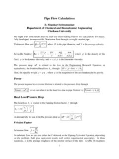
6 Discharge times may vary by no more than 1 second predicted to actual. SINGLE POINT FLOW CALCULATIONS Page - 3 To start out our calculation of density as a function of pressure, we first consider the discharge of the agent from the storage container. We assume that the agent leaves the storage container as pure liquid with appropriate amounts of nitrogen in solution. We assume constant entropy conditions as each increment of liquid leaves the storage container. Pressure recession curves such as those shown for FE13 (HFC23) or FM200 (HFC227ea) may be calculated. FE13 PRESSURE RECESSION IN CYLINDER ASSUMING CONSTANT ENTROPY4004254504755005255505756006250 102030405060708090100 PERCENT DISCHARGEDPRESSURE (PSIA)30 lb/cu ft. Here we see a theoretical cylinder pressure recession based on constant entropy condition for FE 13 (HFC23) discharge.
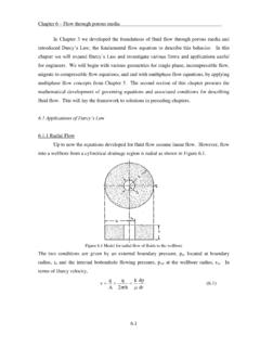
7 Cylinder fill density affects the recession. Fill densities of 30, 40 and 49 pounds per cubic foot are shown. SINGLE POINT FLOW CALCULATIONS Page - 4 NITROGEN SUPERPRESSURIZED FM200 CYLINDER PRESSURE RECESSION CONSTANT DISCHARGEDPRESSURE (PSIA)70 FT. Here we see similar theoretical curves for FM200 superpressurized with nitrogen. HFC227ea (FM200) DISCHARGE TEST 170 LB/CU FT FILL DENSITY050100150200250300350400012345678 910111213 TIME (SEC)PRESSURE (PSIG)CYLINDERNOZ 1 This pressure versus time tracing taken during a FM200 discharge shows the continual variation in cylinder pressure and a lesser variation in pressure at the SINGLE POINT FLOW CALCULATIONS Page - 5 nozzle during the course of discharge. The peak in the nozzle pressure trace at seconds indicates a change from two-phase flow to vapor flow.
8 Both the theoretical and experimental data indicate that pressure in the storage cylinder will vary considerably from the start of discharge until the end. Two basic approaches were considered and tested for calculating the essential hydraulic parameters of flow rate and pressure drop. One approach is to do multiple CALCULATIONS for increments of agent leaving the cylinder. Any number of increments could be chosen -- for example, a calculation could be done for each 10% increment to leave the cylinder. The other approach is to work toward an average condition during the discharge and do a SINGLE calculation based on the average condition. Intuitively one would expect that doing multiple CALCULATIONS for increments leaving the cylinder would yield more accurate results. This is true for relatively simple systems -- yet for simple systems, the accuracy achieved by doing a SINGLE calculation is extremely good -- much better than that required by the ANSI standard.
9 For complex systems, involving unbalanced flow splits at tees, a difficulty with any theoretical approach surfaces -- and this difficulty obviates any advantage in the accuracy which might be gained by the multiple increment approach. PIPELINE PRESSURE AND AGENT DENSITYIn determining a SINGLE POINT in the discharge which approximates an overall average condition of flow, consider that in a well designed system the conditions at the discharge nozzle will control the agent flow rate. A good average condition would be approximated by the mid discharge condition at the nozzles. Neglecting initial transient conditions, the mid discharge condition will be the POINT in time at which of the agent has been discharged from the nozzle. The reference POINT on the cylinder pressure recession curve for the mid discharge condition will vary depending on the amount of agent which the pipeline contains.
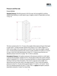
10 SINGLE POINT FLOW CALCULATIONS Page - 6 FM200 CYLINDER PRESSURE RECESSION 70 LB/CU FT FILL DENSITY0501001502002503003504000%10% 20% 30% 40% 50% 60% 70% 80% 90% 100%PERCENT DISCHARGED FROM CYLINDERPRESSURE (PSIA)0% AGENT IN PIPE50% AGENT DISCHARGED MID-DISCHARGE PRESSURE IN CYLINDER If the discharge nozzle is close coupled to the storage cylinder outlet, the pipe will hold zero agent during discharge. 50% of the agent will have left the nozzle basically when 50% of the agent leave the cylinder. This graph shows mid discharge storage cylinder pressure for such an FM200 CYLINDER PRESSURE RECESSION 70 LB/CU FT FILL DENSITY0501001502002503003504000%20%40%6 0%80%100%PERCENT DISCHARGED FROM CYLINDERPRESSURE (PSIA)20% AGENT IN PIPE50% AGENT DISCHARGED FROM THE NOZZLEMID-DISCHARGE PRESSURE IN CYLINDER SINGLE POINT FLOW CALCULATIONS Page - 7 Most often there will be considerable pipe between the cylinder outlet and the discharge nozzles.