Transcription of Single Pole and 3-Way Wide View Motion Activated Light …
1 WARNINGS AND CAUTIONS: TO AVOID FIRE, SHOCK, OR DEATH; TURN OFF POWER AT CIRCUIT BREAKER OR FUSE AND TEST THAT THE POWER IS OFF BEFORE WIRING! To be installed and/or used in accordance with electrical codes and regulations. To avoid overheating and possible damage to this device and other equipment, DO NOT install to control a receptacle, a motor, or a transformer-operated appliance other than applicable specified lighting load: Incandescent and LED. When using in a 3-Way application use one sensor and one standard 3-Way switch .
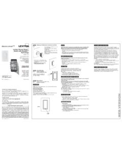
2 Cannot be used with another sensor, or in a 4-way AND CAUTIONS: If you are not sure about any part of these instructions, consult an electrician. Clean outer surface gently with damp cloth only. DO NOT use soaps or cleaning liquids. No user serviceable components. DO NOT attempt to service or repair. Use this device WITH COPPER OR COPPER CLAD WIRE 20 3 Push down tabs per diagram, one at a time and rotate forward to release1 20 31 20 3 Attach new face by inserting bottom hinge tabs, then pivot and snap the color kit to attach TOOLS NEEDED TO INSTALL YOUR DEVICES lotted/Phillips Screwdriver Electrical Tape Pliers Pencil Cutters RulerChanging the color of your device:Your device may include color options.
3 To change color of the face proceed as follows:BKRD3-WayTerminalScrew markedRed (RD)2 TerminalScrew markedBlack (BK)BrassTerminal ScrewMarked 3-WayTerminal Label:Use Terminal for 3-Way Applications Single Pole Applications, Do Not Remove This (Green Screw)SensorSingle Pole and 3-Way Wide View Motion Activated Light ControlCat. No. IPS06, IPV06 - INDOOR USE ONLYR atings: 120 VAC, 60Hz 600W Incandescent & 150W LEDINSTALLATION INSTRUCTIONSPK-93978-10-00-2A FEATURES Cat. No. IPS06 and IPV06 have a sensing area of coverage of 30 ft.
4 X 30 ft., and a sensing angle of 180O (see sensing Area Coverage figure on page 2). Adjustable Light and time-delay controls are located on the front of the device (See adjustment setting section on page 2 for details). LED indicator is used to alert the user of the status of the device. Adjustable Time Delay setting for 30 seconds, 5 min, 15 min & 30 min. occupancy sensor can be converted to a vacancy sensor (See adjustment settings on page 2). LOCATION / MOUNTINGThe device responds to temperature changes and care should be taken when mounting the device.
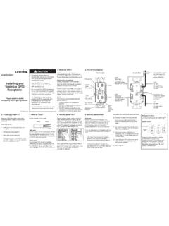
5 DO NOT mount directly above a heat source, in a location where hot or cold drafts will blow directly on the sensor, or where unintended Motion ( , hallway traffic) will be within sensor s is located in electrical box with LINE connection:CHot (Black)Neutral (White)BKLOADLine120 VAC60 HzSensorGreenGround3-Way/Brass3-Way SwitchCommon Terminal(Black Screw)PigtailPigtailGreenGroundRDFirst TravelerSecond TravelerHot (Black)Neutral (White)BKLOADLine120 VAC60 HzSensorGreenGroundGreenGround3-Way/Bras s3-Way SwitchCommon Terminal(Black Screw)PigtailPigtailFirst TravelerSecond TravelerRDBKRD3-Way23-Way Switch2 Sensor135 CommonTerminal(BlackScrew)Ground(Green Screw)14435 CommonTerminal(BlackScrew)Ground(Green Screw)
6 BKRD3-Way2 Sensor35143-Way Switch21543 BSensor is located in electrical box with LOAD connection:WIRING switch :Connect wires per WIRING DIAGRAM as follows: Green or bare copper wire in wall box to Green terminal screw. One pigtail wire to the Black screw terminal marked "COM" and one pigtail wire to the Brass terminal (same side of switch ). Connect the following 4 wires using an appropriately sized wire nut: 1. Common/Line wire (identified in step 2). 2. Second Traveler wire (note color from step 2).
7 3. Two pigtail wires from the 3-Way switch . First Traveler wall box wire (note color from step 2) to Brass screw terminal on the switch (opposite side from the Black screw).WIRING SENSOR:Connect wires per WIRING DIAGRAM as follows: Green or bare copper wire in wall box to Green terminal screw. Common/Load wall box wire identified when removing old switch (step 2) to terminal screw marked "BK". First Traveler wall box wire (note color from step 2) to terminal screw marked " 3-Way ". Second Traveler wall box wire (note color from step 2) to terminal screw marked "RD".
8 This Traveler from the switch must go to the terminal screw on the sensor marked "RD".WIRING SENSOR:Connect wires per WIRING DIAGRAM as follows: Green or bare copper wire in wall box to Green terminal screw. Common/Line wall box wire identified when removing old switch (step 2) to terminal screw marked "BK". First Traveler wall box wire (note color from step 2) to terminal screw marked "RD". Second Traveler wall box wire (note color from step 2) to terminal screw marked " 3-Way ".WIRING switch :Connect wires per WIRING DIAGRAM as follows: Green or bare copper wire in wall box to Green terminal screw.
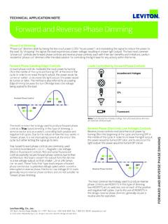
9 One pigtail wire to the Black screw terminal marked "COM" and a one pigtail wire to the brass terminal (same side of switch ) Connect the following 4 wires using an appropriately sized wire nut: 1. Common/Load wire (identified in step 2). 2. First Traveler wire (note color from step 2). 3. Two pigtail wires from the 3-Way switch . Second Traveler wall box wire (note color from step 2) to Brass screw terminal on the switch (opposite side from the Black screw).IMPORTANT: For 3-Way applications, note that one of the screw terminals from the old switch being removed will usually be a different color (Black) or labeled Common.
10 Tag that wire with electrical tape and identify as the common (Line or Load) in both the sensor wall box and remote wall Line or Load (See important instruction below)2. Neutral3. Ground4. First Traveler note color5. Second Traveler note color2431 Single -Pole1. Line (Hot)2. Neutral3. Ground4. Load Step 2 Identifying your wiring application (most common):NOTE: If the wiring in the wall box does not resemble any of these configurations, consult an and connecting wires:This device can be wired using side wire terminal screws.