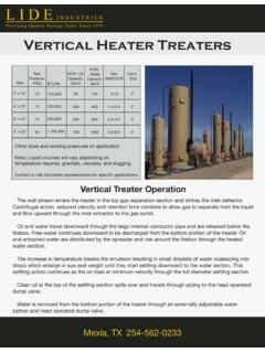
Transcription of Single Stage Vertical In-Line Centrifugal Pumps for ...
1 4600 West Dickman Road, Battle Creek, Michigan 49015 Telephone: (269) 966-4600 Fax: (269) 962-5447 Model VLK PRODUCT MANUAL Single Stage Vertical In-Line Centrifugal Pumps for General Service, Petroleum and Petrochemical Applications API 610 Pump Serving the World Since Document Number: VLK-0000 Date: October 25, 2007 Model VLK Centrifugal Pump API-610 Standard SUPERSEDES ALL PREVIOUS ISSUES 1 of 2 DOCUMENT NUMBER: VLK-0020 October 25, 2007 GENERAL DESCRIPTION VLK - an advanced design Single Stage Vertical In-Line Centrifugal Pump with exceptional flexibility and versatil-ity to meet the requirements of a wide variety of pumping applications.
2 The unit is ruggedly designed for mini-mum maintenance and to meet the heavy-duty requirements of continuous duty operation of general industry, as well as, API 610 applications. STANDARD FEATURES 1 Pump Casing: In-Line mounted casings withstand API 610 nozzle loads. Double volute casings (3" nozzle size and lar-ger) ensure low vibration and radial loads. Latest 3-D modeling and mold flow techniques are used to ensure consistent high quality castings. 2 Flanges: 300 lb. RF per ANSI and API 610 standards. Optional surface finish and ratings available. 3 Casing / Cover: Casing to Cover register fit is a metal to metal fit with fully confined, controlled compression gasket ensures proper sealing and alignment.
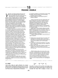
3 Spiral wound 300 Se-ries stainless steel gasket standard. Alternate materi-als available to suit application. 4 Casing Drain: (not shown) Casing can be completely drained. Drain valves op-tional. 6 7 12 8 1 3 2 14 9 10 115 2 Model VLK Centrifugal Pump API-610 Standard SUPERSEDES ALL PREVIOUS ISSUES 2 of 2 DOCUMENT NUMBER: VLK-0020 October 25, 2007 5 Suction Nozzle: Flow straightening vane reduces inlet swirl and en-sures uniform flow to the impeller eye. 6 Impeller: Closed, Single suction Impeller designed to provide low suction specific speeds (Nss<11,000).
4 Low NPSHR impellers available. Streamlined impeller locknut for improved suction performance. Impellers are dynamically balanced to API 610 re-quirements for low vibration and smooth, trouble free operation. Impeller secured to Shaft by Impeller Nut and Set-screw. 7 Wear Rings: Renewable casing and impeller wear rings are held in place by locking pins or setscrews. No back wear ring design optional. Composite reduced clearance wear rings for improved efficiency are optional. 8 Throat Bushing: Close clearance design carbon Throat Bushing pro-vides additional Shaft support and helps provide opti-mum seal chamber environment.
5 9 Seal: Available with reliable, low cost standard mechanical seals or cartridge type mechanical seals for precise seal face setting and ease of maintenance. Stainless steel shaft sleeve and gland plate are standard. 10 Seal Chamber: Designed to API 610 and API 682 Table 2, Table 1 optional. Accepts all mechanical seal arrangements, Sealing system computer modeling and close coordi-nation with seal manufacturers ensures optimum seal chamber environment. Most Seals can be removed without disturbing the Driver. 11 Shaft Arrangement: Gruop I and II VLK s use a soild 12% chrome shaft without a shaft sleeve.
6 This design feature allows complete replacement at less cost than a shaft with sleeve. It also provides greater shaft stiffness than would be obtained if the shaft diameter were to be re-duced for a sleeve. In addition to these advantages, elimination of the shaft sleeve also eliminates a poten-tial leak path. Maximum interchangeability is achieved by using only one shaft for the entire VLK mechanical group. 12 Motor Support Housing: Heavy Duty Motor Support with register fits at the Casing Cover and Driver for precise alignment. 13 Soleplate: (not shown) Optional soleplate provides mounting flexibility.
7 14 Coupling: Three Coupling designs available: VLK Standard Rigid Guaranteed repeatability - ensuring factory stan-dard alignment and run-out. Proven two (2) piece design allows for simplicity of installation and removal. No special alignment or manual fitting procedures are required, as on other multiple-component couplings. Shaft run-out at Seal Chamber is maintained within API 610 tolerances, ensuring optimum Me-chanical Seal performance. Lowest L3/D4 ratios provide maximum rotor stiff-ness and minimum Shaft deflection. AGMA 515 Class 8 balance for low vibration.
8 Stainless Steel construction. Coupling guard fabricated from non-sparking ma-terials. VLK-L Extended Rigid Same quality, reliability and repeatability as the VLK Standard Rigid design. Increases Shaft separation between motor shaft and pump shaft to allow cartridge type mechanical seal to be removed without disturbing the driver or piping. Maintains rotor stiffness that exceeds API 610 cri-teria. VLK-X Back Pull-Out Same quality, reliability and repeatability as the VLK Standard Rigid design. Casing mounted Motor Support allows rotor (Cover, Impeller, Shaft and Seal) removal without disturbing the driver.
9 Maintains rotor stiffness that exceeds API 610 cri-teria. Model VLK Centrifugal Pump API-610 Standard SUPERSEDES ALL PREVIOUS ISSUES 1 of 1 DOCUMENT NUMBER: VLK-0140 October 25, 2007 Cross Sectional Details Reference Drawing # SEC-E0142015 Part Number Description Part Number Description 800 Casing 815-2 Seal Gland O Ring 802 Casing Cover 818 Coupling - Rigid Spacer Type 805 Impeller 820 Shaft 806-1 Impeller Wear Ring - Eye Side (Front) 821-1 Impeller Lock Nut 806-2 Impeller Wear Ring - Hub Side (Back) 823 Mechanical Seal Assembly 808-1 Casing Wear Ring - Eye Side (Front) 824 Adjusting Stud 808-2 Cover Wear Ring - Hub Side (Back)
10 825 Locating Ring 811-1 Impeller Key 828 Spacer Washers 811-2 Shaft Key 847 Throat Bushing 815-1 Casing Gasket 870 Motor Support Model VLK Centrifugal Pump API-610 Standard SUPERSEDES ALL PREVIOUS ISSUES 1 of 2 DOCUMENT NUMBER: VLK-0080 October 25, 2007 Maximum Allowable Nozzle Loading - Side Suction / Side Discharge Both users and manufacturers are concerned with the amount of pipe loads a Centrifugal Pump can with-stand without affecting it s operation. The customer would, of course, be most pleased if Centrifugal Pumps would withstand unlimited pipe strains. As manufacturers, we would like to see no external forces acting on our Pumps at all.