Transcription of SITRANS P Transmitters for differential pressure and flow
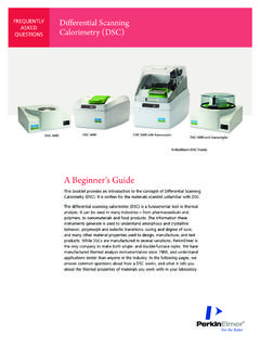
1 Seite 28 Freitag, 17. Dezember 1999 2:35 14. SITRANS P. Transmitters for differential pressure and flow Introduction HK series DS series with PROFIBUS-PA. Fig. 1/16 SITRANS P Transmitters for differential pressure and flow, with built-in analog indicator or digital display Application 12 14. The transmitter measures 00 00000. HK series the differential pressure , M. low pressures above or below atmospheric pressure , 13. the flow q ~ D p (in conjunction with a primary differential pressure device) 15 14. 00000. of gases, vapors and liquids. Different spans are possible de- 00.
2 Pending on the version. DS series M. The output signal is a load-independent direct current of 4 to 13. 20 mA or a digital bus signal where a linear characteristic (pro- portional to the differential pressure ) or a square-rooted charac- teristic (proportional to the flow) can be selected. 8 9 10 11. mC I A, U H. Transmitters conforming to the type of protection "Intrinsic safe- ty" and "Explosion-proof" may be installed within potentially ex- plosive atmospheres (zone 1). The conformity certificate + differential pressure corresponds to the European standard (CENELEC), the Ameri- 5 6 7.
3 - IA. } as input variable Output signal can standard (FM) or the Canadian standard (CSA). UH Power supply The Transmitters can be equipped with various designs of re- 1 Process flange mote seals for special applications such as the measurement of 2 Body of measuring cell highly viscous substances. 3 Filling liquid 4 Seal diaphragm 4 4. - + 5 O-ring Adjustable spans 1. 6 Center diaphragm 7 Silicon pressure sensor Series Span in bar 8 Instrument amplifier 3 2 9 Analog-to-digital converter 1 to 30,000. 10 Microcontroller HK 11 Digital-to-analog converter or DS PROFIBUS-PA interface 12 Digital display for DS (PA) Measuring cells from 20 mbar to 30 bar parameterization 13 Keys for parameterization Types of protection and conformity certificates 14.
4 15. Analog indicator (option). Digital display for parameterization Series Type of protection Conformity certificate and measured value Intrinsic Explosion- CENELEC FM/CSA. safety proof Fig. 1/17 Functional diagram HK 4 4. DS 4 4 4 4. DS (PA) 4 4 4 o 4 = Exists o = In planning 1/28 Siemens FI 01 2000. Seite 29 Freitag, 17. Dezember 1999 2:35 14. SITRANS P. Transmitters for differential pressure and flow Introduction Mode of operation Elements for parameterization of transmitter The differential pressure is applied via the seal diaphragm (4, Parameterization using HK DS. Fig.)
5 1/17) and the filling liquid (3) to the silicon pressure sensor 3 external keys 4 4. (7). If the measuring limits are exceeded, the overload dia- phragm (6) is flexed until one of the seal diaphragms (4) rests on Built-in digital display 4 4. the measuring self body (2), thus protecting the silicon pressure Laptop, PC 4. sensor (7) from overloading. HART communicator 4. The measuring diaphragm is flexed by the applied differential PROFIBUS-PA interface 4. pressure . The resistance of four piezo-resistors fitted in the dia- phragm in a bridge circuit thus changes. This change in resis- Adjustable parameters which can also be displayed tance results in a bridge output voltage proportional to the differential pressure .
6 This voltage is amplified and converted into HK DS. a digital signal by means of an analog-to-digital converter (9). Start-of-scale and full-scale values This signal is evaluated by a microcontroller (10), and its linearity 4 4. with application of a pressure and temperature response corrected. The signal processed in Start-of-scale and full-scale values without this manner is converted in a digital-to-analog converter (11) into 4 4. application of a pressure ("Blind setting"). an output current of 4 to 20 mA, or via the PROFIBUS-PA inter- Characteristic (linear or square-rooted) 4 4.
7 Face into a digital bus signal. Application point of square-rooted characteristic 4 4. The data specific to the measuring cell as well as the data for pa- Damping 4 4. rameterization of the transmitter are stored in a non-volatile EE- Current transmitter function 4 4. PROM. Zero adjustment 4 4. Parameterization Output signal in event of fault 4 4. Disabling of keys for operation 4 4. Depending on the version, there are different possibilities for pa- Measured-value display in % or mA 4 4. rameterizing the transmitter and for setting or scanning the pa- rameters. Measured-value display of physical unit 4.
8 Measuring-point number (abbreviation, max. 16. Parameterization using the input keys (local operation) 4. characters). The input keys can be used to simply set the most important pa- Measuring-point description (max. 27 charac- rameters without any additional equipment. ters). 4. Parameterization using HART communicator Message 4. When parameterizing with the HART communicator, the connec- Range limits 4. tion is made directly to the two-wire system (Fig. 1/18). When pa- transmitter version ( material) 4. rameterizing with a laptop or PC, the connection is made via a HART modem (Fig.)
9 1/19). Slave pointer (only PROFIBUS-PA) 4. Further displays and parameters 4. The signals required for communication according to the HART. protocol are superimposed on the output current according 4 Possible to frequency shift keying (FSK). +. SITRANS P 230 to 1100 W Power supply transmitter Parameterization via PROFIBUS-PA interface SITRANS P Transmitters with a PROFIBUS-PA interface HART. communicator (Fig. 1/20) are parameterized, starting from a master, using signals transmitted via PROFIBUS-DP and converted by a SIMATIC DP/PA coupler with power supply into a signal for Fig.
10 1/18 Communication between HART communicator and transmitter PROFIBUS-PA. A bus terminator is required for cable lengths > 2 m. PROFIBUS-DP PROFIBUS-PA. T. SITRANS P 230 to 500 W Power supply Bus ter- transmitter Master minator +. PC or HART Laptop modem Coupler with .. power supply RS 232 transmitter with PROFIBUS-PA interface Fig. 1/19 Communication between PC or laptop and transmitter Fig. 1/20 Communication via PROFIBUS-PA interface Siemens FI 01 2000 1/29. Seite 30 Freitag, 17. Dezember 1999 2:35 14. SITRANS P. Transmitters for differential pressure and flow Technical data Technical data HK DS DS with PROFIBUS-PA.