Transcription of SJ200 Series Inverter Quick Reference Guide - …
1 SJ200 Series Inverter Quick Reference Guide Single-phase Input 200V Class Three-phase Input 200V Class Three-phase Input 400V Class Hitachi Industrial Equipment Systems Co., Ltd. Manual No. NB6501XA March 2004. Caution: Be sure to read the SJ200 Inverter Manual and follow its Cautions and Warnings for the initial product installation. This Quick Reference Guide is intended for Reference use by experienced users in servicing existing installations. Power Circuit Terminals Inverter models SJ200 002 NFEF/NFU to 005 NFEF/NFU.
2 Jumper RB +1 + . L1 L2 N/L3 U/T1 V/T2 W/T3. Chassis Ground Inverter models SJ200 007 NFEF to 022 NFEF, 007 NFU to 037 LFU, 004 HFEF/HFU to 040 HFEF/HFU. Jumper +1 + RB. NFEF, NFU. L1 L2 N/L3 U/T1 V/T2 W/T3. LFU, HFEF, HFU. L1 L2 L3 U/T1 V/T2 W/T3. Chassis Ground Inverter models 055 HFEF/HFU, 075 HFEF/HFU. L1 L2 L3 U/T1 V/T2 W/T3. +1 + RB. Jumper Chassis Ground 1. Control Circuit Terminals Logic inputs L 6 5 4 3 2 1 PCS. Alarm relay AL2 AL1 AL0. Analog Logic Analog outputs inputs outputs H O OI L AM CM2 12 11. Terminal Name Description Ratings and Notes PCS +24V for logic inputs 24 VDC supply, 30 mA max.
3 (Notes: Do not use for network power Do not short to terminal L). 1, 2, 3, 4, Intelligent (program- 27 VDC max. (use P24 or an 5, 6 mable) discrete logic external supply referenced to inputs terminal L), input impedance L (top GND for logic inputs Sum of input 1 to 6 currents row) (Note: Do not ground). 11, 12 Discrete logic outputs 50 mA max. ON current, 27 VDC max. OFF voltage CM2 GND for logic outputs 100 mA max for sum of terminals 11 and 12 currents AM Analog voltage output 0 to 10 VDC, 1 mA max., 50%. duty cycle L (bottom GND for analog signals Sum of OI, O, H, and AM.)
4 Row) currents (return). OI Analog input, current 4 to mA range, 20 mA. nominal 2. Terminal Name Description Ratings and Notes O Analog input, voltage 0 to VDC range, 10 VDC. nominal, 12 VDC max., input impedance 10 k . H +10V analog Reference 10 VDC nominal, 10 mA max. AL0 Relay common contact Contact rating Max resistive load = 250 VAC, AL1 Relay contact, normally ; 30 VDC 3A;. closed during RUN Max inductive load = 250 VAC, ; 30 VDC AL2 Relay contact, normally Minimum load = 5 VDC 100mA, open during RUN 100 VAC 10mA.
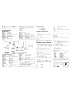
5 3. Basic Wiring Diagram The following wiring diagram shows the power and motor connections for basic operation. The optional signal input wiring supports external Fwd and Rev Run command, and a speed potentiometer. SJ200 . From 3-phase power input R U. (L1) (T1). source (See specifications S V. label on Inverter Motor (L2) (T2). for details). T W. (N/L3) (T3). Inputs: PCS AL1. Forward Relay contacts, 1 AL0 1 Form C. Reverse 2 AL2. Open collector GND for logic inputs L outputs: Run signal 12. Load Analog Reference H Load External speed Reference O Frequency pot.
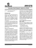
6 11 arrival signal L GND for logic outputs GND for analog signals CM2. 4. Inverter Keypad Operation Run Key Enable LED Parameter Display Program/Monitor LED. Run/Stop LED Power LED. Alarm LED. POWER. HITACHI. 5 ALARM Display Units LEDs Hz HITACHI Hertz A Amperes RUN. RUN STOP PRG. RESET. Potentiometer Enable LED. FUNC 1 2 STR Potentiometer Stop/Reset Key Run Key Up/Down Keys Store Key Function Key Run/Stop LED ON when the Inverter output is ON and the motor is developing torque, and OFF when the Inverter output is OFF (Stop Mode).
7 Program/Monitor LED ON when the Inverter is ready for parame- ter editing (Program Mode). It is OFF when the parameter display is monitoring data (Monitor Mode). Run Key Enable LED ON when the Inverter is ready to respond to the Run key, OFF when the Run key is disabled. Run Key Press this key to run the motor (the Run Enable LED must be ON first). Parameter F004, Keypad Run Key Routing, determines whether the Run key generates a Run FWD or Run REV command. Stop/Reset Key Press this key to stop the motor when it is running (uses the programmed deceleration rate).
8 This key will also reset an alarm which has tripped. Potentiometer Allows an operator to directly set the motor speed when the potentiometer is enabled for output frequency control. Potentiometer Enable LED ON when the potentiometer is enabled for value entry. (continued, next ). 5. Parameter Display A 4-digit, 7-segment display for parameters and function codes. Display Units: Hertz/Amperes One of these LEDs will be ON to indicate the units associated with the parameter display. Power LED ON when the power input to the Inverter is ON.
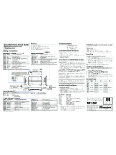
9 Alarm LED ON when the Inverter in Trip Mode. Function Key This key is used to navigate through the lists of parameters and functions for setting and monitoring parameter values. Up/Down Keys Use these keys alternately to move up or down the lists of parameter and functions shown in the display, and to increment/. decrement values. Store Key When the unit is in Program Mode and the operator has edited a parameter value, press the Store key to write the new value to the EEPROM. 6. Keypad Navigation Map Monitor Mode Program Mode Display data Select Parameter Edit Parameter powerdown FUNC.
10 H007 Store as powerup d083 1 2 default 1 2 h003. Increment/. d 001 1 2. decrement 1 2 c1 48 value H 1 2 1 2. 1 2 c 001 Edit C 1 2 FUNC. FUNC. 1 2 1 2 b1 5 0. FUNC. b 1 2 STR. 1 2 b001 Write data to A 1 2 EEPROM. 1 2 A1 46. F 004 FUNC. 1 2. 1 2 A001. Return to F 001 parameter list 7. Powerup Test The Powerup Test procedure uses minimal parameter settings to run the motor. The procedure describes two alternative methods for commanding the Inverter : via the Inverter keypad, or via the logic terminals. Check power input and motor output wiring (see page 4 diagram).