Transcription of SKF Disc Couplings
1 SKF disc CouplingsThe SKF disc coupling is the ideal solution in medium to high torque applications that require torsional rigidity, offer some allow-ance for misalignment, and do not require lubrication. These applications typically have a capacity range up to 178 kNm in a range of configurations including single disc , dou-ble disc , and spacer for both horizontal and vertical mounting. Standard shaft capacities are up to 289 mm. The SKF disc coupling consists of two hubs and a laminated stainless steel disc pack secured by a series of fitted bolts retained by nylon insert lock nut nuts.
2 For spacer units, the spacer length is held between two disc pack sets. Single disc units can accommodate angular (a) offset only. Double disc pack units, with a spacer, will allow for angular (a), parallel (d), or combined offset. Both configurations will also allow for some axial (d) disc pack, or spacer may be removed and re-installed radially, meaning the prime mover and driven machine need not be moved at all-steel machined components allow for high speed applications to be handled with ease. With two-plane dynamic balancing, higher speeds are often are carried with pilot bores so that boring to requirements is easy.
3 In addition, where zero backlash is required, the use of the SKF FX Keyless Bushing is a simple and economical SKF disc coupling offers the following benefits: Medium to high torque capability Cost effective (v torque and size) No lubrication required No frictional or energy losses Quiet operation (no meshing) Zero backlash Angular misalignment (ac) Parallel offset (b) with spacer / double disc pack configuration only High speed capability (may require dynamic balancing over 50 m/s) Limited end-float / axial movement (d) Temperature-tolerant (generally up to 250 C) Low inertia / mass MK2 (when compared with other metallic-type Couplings )
4 Various hub designs, including short or inverted hub Standard spacer lengths to ANSI and ISO standards generally available Available with longer tubular spacers (steel or composite in some instances) Ease of mounting / alignment and maintenanceCoupling typesThe SKF disc coupling is available in 2 basic configurations: Single disc Double disc Short spacer Standard spacer Custom spacer Floating horizontal Floating verticalSelection Standard selection methodThis selection method can be used for most motor, turbine or engine-driven applica-tions, with appropriate service and duty following information is required to select an appropriate SKF disc coupling .
5 Power (kW) Speed (r/min) Torque (Nm) Type of driven equipment Application and duty cycle Shaft diameters (or at least the maximum bore) Shaft gap (DBSE) Space limitations (if any) Other ambient conditions, such as temperature adverse environmentWhere applications involve reversing or braking torque, please contact your local SKF technical expert for Determine the torque of the system, using Formulae kW x 9 550 MT = r/minwhere MT Torque (moment) [Nm]kW Motor or demand power (kW)r/min Revolutions per minute [min 1]2 From the service factor tables ( page 89), select a suitable service factor (FS)
6 For the Determine the minimum torque require-ment (MC) for the coupling by multiplying the torque determined in (1), by the ser-vice factor selected in (2): MC = MT x FSThe coupling must have a torque capacity equal to or greater than this resultant MC Check the bore size capacity for both shafts. If the bore size is too small, a larger cou-pling may be required to accommodate the Check to make sure other parameters such as maximum permissible speed and any dimensional limitations are all selection exampleSelect a coupling to connect a 30 kW, 1 440 r/min electric motor to a cooling tower fan (force draft).
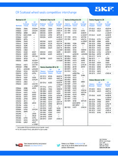
7 The motor shaft is 48 mm, and the pump shaft 55 mm. A spacer type is required of approx. 4" (101,6 mm) for ease of maintenance. Max-imum temperature is 60 degrees, with other 45space limitations. Operation is 10 12 hours a Determine the torque of the system: 30 x 9 550 MT = = 199 Nm 1 4402 Determine the service factor from page the type of application the FS is The minimum required coupling capacity rating (MC) is 2,0 x 199 = 398 coupling capacity must be equal to or greater than this From the tables on page 52, a type PHE W4D-030 is capacity 774 NmMax.
8 Shaft Dia 58 mmSpacer (standard) 102 mmMaximum r/min 7 300 r/min 5 Selection summary:Type PHE W4D-030X102 MMX48X55 Complete with 102 mm spacer (standard) and hubs bored to 48 mm (H7) and 55 mm (H7) respectively. Note: If no tolerances are given, the standard SKF bore diameter tolerances given in table 4 ( page 85) will be stated otherwise, all bores come with standard (ISO Metric, or BS INCH) keyways. In some instances a shallow key may be necessary (Metric DIN 6885/3).Engineering dataFor additional useful information on disccouplings, such as characteristics and applications of disc Couplings .
9 Please, refer to the following dataA disc coupling exists at least of 2 hubs and 1 disc pack and bolt kit. The number of required disc pack and bolt kits depend on coupling type. Vertical kits and vertical spacer kits might also be needed. For details refer to table 1 disc coupling series designationTypeDescription4 Bolt6 Bolt8 BoltSingle discStandardW4 DoubleShort spacerW4SD Standard spacerW4DW6DW8 DCustom spacerW4FW6FW8 FFloatingHorizontalW4 FHW6 FHW8 FHVerticalW4 FVDW6 FVDW8 FVD46 Table 4 Order dataCoupling typeHubsDisc packBolt kitVertical kitSpacer / Vertical kit (VKIT) Solid boreQtyBored to size1)Qty Qty Qty Qty(.
10 = DBSE dimension)QtySingle-flex (W4)PHE W4-15 HUBRSB2 orPHE W4-15 DPACK1 PHE W4-15 KIT1 Double-flex (W4), with spacerPHE W4-15 HUBRSB2 orPHE W4-15 DPACK2 PHE W4-15 KIT2 PHE floatingPHE W6-35 HUBRSB2 orPHE W6-35 DPACK2 PHE W6-35 KIT2 PHE semi-floatingPHE W6-35 HUBRSB2 orPHE W6-35 DPACK1 PHE W6-35 KIT1 PHE (vertical)PHE W4-15 HUBRSB2 orPHE W4-15 DPACK1 PHE W4-15 KIT1 PHE W4-15 VKIT1 Double-flex (vertical) with spacerPHE W6-35 HUBRSB2 orPHE W6-35 DPACK2 PHE W6-35 KIT2 PHE W6-35 VKIT1 PHE floating (vertical)PHE W6-35 HUBRSB2 orPHE W6-35 DPACK2 PHE W6-35 KIT2 PHE W6-35 VKIT1 PHE complete coupling designation consists of the series, size and bore details.