Transcription of SLAB DESIGN - The University of Memphis
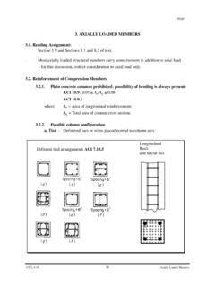
1 1 slab DESIGN Reading Assignment Chapter 9 of Text and, Chapter 13 of ACI318-02 Introduction ACI318 Code provides two DESIGN procedures for slab systems: Direct DESIGN Method (DDM) For slab systems with or without beams loaded only by gravity loads and having a fairly regular layout meeting the following conditions: There must be three or more spans in each directions. Panels should be rectangular and the long span be no more than twice the short span. Successive span lengths center-to-center of supports in each direction shall not differ by more than 1/3 of the longer span. Columns must be near the corners of each panel with an offset from the general column line of no more 10% of the span in each direction. The live load should not exceed 3 time the dead load in each direction.
2 All loads shall be due gravity only and uniformly distributed over an entire panel. If there are beams, there must be beams in both directions, and the relative stiffness of the beam in the two directions must be related as follows: where cb bcs sEIEI = is the ratio of flexural stiffness of beam sections to flexural stiffness of a width of slab bounded laterally by center lines of adjacent panels (if any) on each side of the beam. 2 For slab systems loaded by horizontal loads and uniformly distributed gravity loads, or not meeting the requirement of the section , the Equivalent Frame Method (EFM) of Sect. of ACI code may be used. Although Sect. of the ACI code implies that the EFM may be satisfactory in cases with lateral as well horizontal loads, the Commentary cautions that additional factors may need to be considered.
3 The method is probably adequate when lateral loads are small, but serious questions may be raised when major loads must be considered in addition to the vertical loads. The direct DESIGN method gives rules for the determination of the total static DESIGN moment and its distribution between negative and positive moment sections. The EFM defines an equivalent frame for use in structural analysis to determine the negative and positive moments acting on the slab system. Both methods use the same procedure to divide the moments so found between the middle strip and column strips of the slab and the beams (if any). Section of the Code could be viewed as an escape clause from the specific requirements of the code. It states: A slab may be designed by any procedure satisfying conditions for equilibrium and geometrical compatibility if shown that the DESIGN strength at every section is at least equal to the required strength considering Secs.
4 And (of the ACI code), and that all serviceability conditions, including specified limits on deflections, are met. The methods of elastic theory moment analysis such as the Finite Difference procedure satisfies this clause. The limit DESIGN methods, for example the yield line theory alone do not satisfy these requirements, since although the strength provisions are satisfied, the serviceability conditions may not be satisfied without separate checks of the crack widths and deflections at service load levels. The thickness of a floor slab must be determined early in DESIGN because the weight of the slab is an important part of the dead load of the structure. The minimum thickness can be determined by many factors: Shear strength of beamless slabs (usually a controlling factor); slab must be thick enough to provide adequate shear strength Flexural moment requirement (less often a governing factor) Fire resistance requirements Deflection control (most common thickness limitations) Section of ACI gives a set of equations and other guides to slab thickness, and indicates that slabs which are equal to or thicker than the computed limits should have deflections within acceptable range at service load levels.
5 ACI code direct DESIGN method and equivalent methods can be conveniently discussed in terms of a number of steps used in DESIGN . The determination of the total DESIGN moment in concerned 3 with the safety (strength) of the structure. The remaining steps are intended to distribute the total DESIGN moment so as to lead to a serviceable structure in which no crack widths are excessive, no reinforcement yields until a reasonable overload is reached, and in which deflections remain within acceptable limits. These steps are discussed as we go along. Equivalent frame method may be used in those cases where: slab layout is irregular and those not comply with the restrictions stated previously where horizontal loading is applied to the structure where partial loading patterns are significant because of the nature of the loading high live load/dead load ratios.
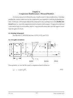
6 4 DESIGN Procedure The basic DESIGN procedure of a two-way slab system has five steps. 1. Determine moments at critical sections in each direction, normally the negative moments at supports and positive moment near mid-span. 2. Distribute moments transverse at critical sections to column and middle-strip and if beams are used in the column strip, distribute column strip moments between slab and beam. 3. Determine the area of steel required in the slab at critical sections for column and middle strips. 4. Select reinforcing bars for the slab and concentrate bars near the column, if necessary 5. DESIGN beams if any, using procedures you learned in CIVL 4135. Positive and Negative Distribution of Moments For interior spans, the total static moment is apportioned between critical positive and negative bending sections as (See ACI 318-02 Sect.)
7 : Panel Moment Mo100% Static MomentNegative Moment Monegative Mu = MoPositive Moment Mopositive Mu = Mo As was shown, the critical section for negative bending moment is taken at the face of rectangular supports, or at the face of an equivalent square support. For the Case of End Span The apportionment of Mo among three critical sections (interior negative, positive, and exterior negative) depends on 1. Flexural restraint provided for slab by the exterior column or the exterior wall. 2. Presence or absence of beams on the column lines. See ACI 318-02 Sect. of ACI 5 6 7 Lateral Distribution of Moments Here we will study the various parameters affecting moment distribution across width of a cross-section. Having distributed the moment Mo to the positive and negative moment sections as just described, we still need to distribute these DESIGN moments across the width of the critical sections.
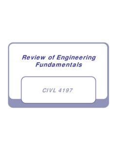
8 For DESIGN purposes, we consider the moments to be constant within the bounds of a middle or column strip unless there is a beam present on the column line. In the latter case, because of its greater stiffness, the beam will tend to take a larger share of the column-strip moment than the adjacent slab . For an interior panel surrounded by similar panels supporting the same distributed loads, the stiffness of the supporting beams, relative to slab stiffness is the controlling factor. The distribution of total negative or positive moment between slab middle strip, column strip, and beams depends on: the ratio of l2/l1, the relative stiffness of beam and the slab , the degree of torsional restraint provided by the edge beam. The beam relative stiffness in direction 1 is: 11cb bcs sEIaEI= where EcbIb1 = Flexural rigidity of beam in direction 1 EcsIs = Flexural rigidity of slabs of width l2 = bh3/12 where b = width between panel centerlines on each side of beam.
9 Similarly 22cb bcs sEIaEI= in general 0a<< a= Supported by walls 0a= no beams for beam supported slabs a < 4 or 5 l2 h 8 Note: Values of a are ordinarily calculated using uncracked gross section moments of inertia for both slab and beam. Beams cross section to be considered in calculating Ib1 and Ib2 are shown below. (see ACI sect. ) The relative restraint provided by the torsional resistance of the effective transverse edge beam is reflected by parameter t such as: 2cbtcs sECEI = where Ecb = Muduls of Elasticity of Beam Concrete C = Torsional Constant of the Cross section The constant C is calculated by dividing the section into its rectangles, each having smaller dimension x and larger dimension y: 3(1 )3xxyCy= Page 207 Fig of ACIE xamples of the portion of slab to be included with the beam under 28wwwfbhbh+ +wbwhfh 9 See Section of ACI for factored moments in column strips.
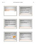
10 Beamless slaby1x2y2y1x1x2y2x1yxcolumnslab1y2y2x1x 1x1y2y2x 10 Positive Moment Pos Mu = M0 Negative Moment Neg Mu = M0 Panel Moment M0 100% Static Moment Column Strip Moment Middle Strip Moment Beam Moment slab Moment Column Strip Moment Middle Strip Moment Beam Moment slab Moment ACI ACI ACI ACI 11 12 13 14 ACI Two-Slabs Depth Limitation Serviceability of a floor system can be maintained through deflection control and crack control Deflection is a function of the stiffness of the slab as a measure of its thickness, a minimum thickness has to be provided irrespective of the flexural thickness requirement. Table (c) of ACI gives the minimum thickness of slabs without interior beams. Table (b) of ACI gives the maximum permissible computed deflections to safeguard against plaster cracking and to maintain aesthetic appearance.