Transcription of Smart Card Tutorial - Part 1 First Published in …
1 Smart card Tutorial - part 1 First Published in september 1992 Introduction To Smart CardsEven the name Smart card captures the imagination, however such a term is ambiguous and isused in many different ways. ISO uses the term, Integrated Circuit card (ICC) to encompass allthose devices where an integrated circuit is contained within an ISO 1 identification card piece ofplastic. The card is x x and is the same as the ubiquitous bank cardwith its magnetic stripe that is used as the payment instrument for numerous financial Circuit Cards come in two forms, contact and contactless.
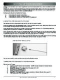
2 The former is easy toidentify because of its gold connector plate (fig 1). Although the ISO Standard (7816-2) definedeight contacts, only 6 are actually used to communicate with the outside World. The Contactlesscard may contain its own battery, particulary in the case of a "Super Smart card " which has anintegrated keyboard and LCD display. In general however the operating power is supplied to thecontactless card electronics by an inductive loop using low frequency electronic magneticradiation.
3 The communications signal may be transmitted in a similar way or can use capacitivecoupling or even an optical 1: ISO ID 1 CardThe Contact card is the most commonly seen ICC to date largely because of its use in France andnow other parts of Europe as a telephone prepayment Most contact cards contain a simpleintegrated circuit although various experiments have taken place using two chips. The chip itselfvaries considerably between different manufacturers and for a whole gambit of applications. Letus consider First the purpose for the 6 contacts used by the ICC (fig 2)Figure 2: ISO 7816-2 ConnectorVcc is the supply voltage that drives the chips and is generally 5 volts.
4 It should be notedhowever that in the future we are likely to see a move towards 3 volts taking advantage ofadvanced semiconductor technology and allowing much lower current levels to be consumed bythe integrated circuit. Vss is the substrate or ground reference voltage against which the Vccpotential is measured. Reset is the signal line that is used to initiate the state of the integratedcircuit after power is in itself an integral and complex process that we shall describe laterin more clock signal is used drive the logic of the IC and is also used as the reference for the serialcommunications link.
5 There are two commonly used clock speeds MHZ and MHZ. Thelower speed is most commonly used to date in Europe but this may change in the future. One maybe tempted to ask why these strange frequencies were chosen, why not just a straight 5 MHZ. Thereason lies in the availability of cheap crystals to form the clock oscillator circuits. Both of thesefrequencies are used in the television world for the colour sub carrier frequency. The PAL systemoperates using MHZ whilst the MHZ is used by the American NTSC standard. The theVpp connector is used for the high voltage signal that is necessary to program the EPROM memory.
6 Last, but by no means least is the serial input/output (SIO) connector. This is the signalline by which the chip receives commands and interchanges data with the outside world. This isalso a fairly complex operation and will be the subject of a more detailed discussion wheresymbols such as T0 and T1 will be fully what does the chip contain, well the primary use of the IC card is for the portable storage andretrieval of data. Hence the fundamental component of the IC is a memory module. The followinglist represents the more commonly used memory types, ROMRead only memory (mask ROM) PROMP rogrammable read only memory EPROME rasable programmable ROM EEPROME lectrically erasable PROM RAMR andom access memoryA particular chip may have one or more of these memory types.
7 These memory types haveparticular characteristics that control their method of use. The ROM type of memory is fixed andcan not be changed once manufactured by the semiconductor company. This is a low costmemory, in that, it occupies minimum space on the silicon substrate. The use of the silicon isoften referred to as real estate because clearly one wants to get as much as possible into thesmallest possible space. The snag however is that it can not be changed and takes several monthsto be produced by the semiconductor company.
8 There is also effectively a minimum orderquantity in order to achieve this low order of increasing real estate the PROM comes next. This memory is programmable by theuser through the use of fusible links. However high voltage and currents are required for theprogramming cycle and such devices are not normally used in Integrated Circuit Cards. TheEPROM has been widely used in the past but the name for this application is something of amisnomer. Whilst the memory is erasable, by means of ultra violet light, the necessary quartzwindow is never available in the ICC and the memory is really used in one time programmablemode (OTP).
9 Getting pretty heavy in real estate terms is the EEPROM. This memory is indeederasable by the user and can be rewritten many times (between 10,000 and 1,000,000 in a typicalimplementation) All of these memories describe so far are non volatile. In other words when thepower is removed they still retain their contents. The random access memory (RAM) is adifferent kettle of fish, this is volatile memory and as soon as the power is removed the datacontents is order to pursue our studies further we must note that the cost of the IC at saturation ( whendevelopment costs have been recouped) is proportional to the square area of silicon used(assuming constant yield).
10 The ISO connector is so designed to constrain the silicon die size toabout 25mm2 (although it is possible to handle 35mm2 or more). However the important point ismore concerned with reliability where clearly the larger die will be more prone to mechanicalfracture. There is another bi- product that we will consider later where the cost of testing andpersonalisation are considerable altered by the complexity of the particular chip. It is clearhowever that we should attempt to minimise the contents of the chip on both cost and reliabilitygrounds commensurate with the particular application.