Transcription of SMART Transmitter Power Supply KCD2-STC-Ex1 …
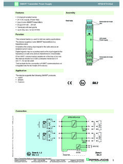
1 Release date 2017-11-09 17:01 Date of issue to "General Notes Relating to Pepperl+Fuchs product Information".Pepperl+Fuchs GroupUSA: +1 330 486 0002 Singapore: +65 6779 9091 Germany: +49 621 776 Transmitter Power SupplyKCD2-STC-Ex17-5-1+2-3+4-6+8+HARTZo ne 2 Div. 2 HART24 V DC9+10- Power Rail24 V DCHARTVmAZone 0, 1, 2 Div. 1, 2250 ConnectionAssembly 1-channel isolated barrier 24 V DC Supply ( Power Rail) Input for 2-wire SMART transmitters and current sources Output for 4 mA .. 20 mA or 1 V .. 5 V Sink or source mode Housing width mm Up to SIL 2 acc. to IEC 61508 FunctionThis isolated barrier is used for intrinsic safety device supplies 2-wire SMART transmitters in a hazardous area, and can also be used with 2-wire SMART current transfers the analog input signal to the safe area as an isolated current signals may be superimposed on the input signal in the hazardous or safe area and are transferred output of current source, sink mode, or voltage output is available via DIP the HART communication resistance in the loop is too low, the internal resistance of 250 between terminals 6 and 8 can be sockets for the connection of HART communicators are integrated into the terminals of the device supports the following SMART protocols: HART BRAIN2 FeaturesPWR9108675S1S3S4S2 III1234 KCD2-STC-Ex1 LED green: Power supplyRemovable terminalsgreen Removable terminalsblueFront viewSwitch 1.
2 4 Place for labelingRelease date 2017-11-09 17:01 Date of issue dataKCD2-STC-Ex12 Refer to "General Notes Relating to Pepperl+Fuchs product Information".Pepperl+Fuchs GroupUSA: +1 330 486 0002 Singapore: +65 6779 9091 Germany: +49 621 776 specificationsSignal type Analog inputFunctional safety related parametersSafety Integrity Level (SIL) SIL 2 SupplyConnection Power Rail or terminals 9+, 10-Rated voltage Ur19 .. 30 V DCRipple 10 %Rated current Ir 45 mAPower dissipation 800 mWPower consumption WInputConnection side field sideConnection terminals 1+, 2-; 3+, 4-Input signal 4 .. 20 mA limited to approx. 30 mAOpen circuit voltage/short-circuit current terminals 1+, 2-: 22 V / 30 mAVoltage drop terminals 3+, 4- : approx. 5 VAvailable voltage terminals 1+, 2-: 15 V at 20 mAOutputConnection side control sideConnection terminals 5-, 6+Load 0.
3 300 (source mode)Output signal 4 .. 20 mA or 1 .. 5 V (on 250 , % internal shunt) 4 .. 20 mA (sink mode), operating voltage .. 26 VRipple 20 mV rmsTransfer characteristicsDeviation at 20 C (68 F) % incl. non-linearity and hysteresis (source mode 4 .. 20 mA) % incl. non-linearity and hysteresis (sink mode 4 .. 20 mA) % incl. non-linearity and hysteresis (source mode 1 .. 5 V)Influence of ambient temperature < 2 A/K (0 .. 60 C (32 .. 140 F)); < 4 A/K (-20 .. 0 C (-4 .. 32 F)) (source mode and sink mode 4 .. 20 mA) < mV/K (0 .. 60 C (32.))
4 140 F)); < 1 mV/K (-20 .. 0 C (-4 .. 32 F)) (source mode 1 .. 5 V)Frequency range field side into the control side: bandwidth with Vpp signal 0 .. 3 kHz (-3 dB) control side into the field side: bandwidth with Vpp signal 0 .. 3 kHz (-3 dB)Settling time 200 msRise time/fall time 20 msGalvanic isolationInput/Output reinforced insulation acc. to EN 50178, rated insulation voltage 300 Veff Input/ Power Supply reinforced insulation acc. to EN 50178, rated insulation voltage 300 Veff Output/ Power Supply reinforced insulation acc. to EN 50178, rated insulation voltage 300 Veff Indicators/settingsDisplay elements LEDC ontrol elements DIP-switchConfiguration via DIP switchesLabeling space for labeling at the frontDirective conformityElectromagnetic compatibility Directive 2014/30/EU EN 61326-1:2013 (industrial locations)ConformityElectromagnetic compatibility NE 21:2006 Degree of protection IEC 60529:2001 Ambient conditionsAmbient temperature -20.
5 60 C (-4 .. 140 F)Mechanical specificationsDegree of protection IP20 Connection screw terminalsMass approx. 100 gDimensions x 114 x 124 mm ( x x inch) , housing type A2 Mounting on 35 mm DIN mounting rail acc. to EN 60715:2001 data for application in connection with hazardous areasEU-Type Examination Certificate CESI 06 ATEX 021 Marking II (1)G [Ex ia Ga] IIC , II (1)D [Ex ia Da] IIIC , I (M1) [Ex ia Ma] IInput [Ex ia Ga] IIC, [Ex ia Da] IIIC, [Ex ia Ma] ISupply Release date 2017-11-09 17:01 Date of issue dataKCD2-STC-Ex13 Refer to "General Notes Relating to Pepperl+Fuchs product Information".Pepperl+Fuchs GroupUSA: +1 330 486 0002 Singapore: +65 6779 9091 Germany: +49 621 776 safe voltage Um250 V AC (Attention!)
6 Um is no rated voltage.)Equipment terminals 1+, 2-VoltageUo VCurrent Io 100 mAPowerPo 630 mWEquipment terminals 3+, 4-VoltageUi < 30 VCurrentIi < 128 mAVoltageUo VCurrent Io 100 mAPowerPo 25 mWCertificate PF 06 CERT 0973 XMarking II 3G Ex nA IIC T4 GcGalvanic isolation Input/Output safe electrical isolation acc. to IEC/EN 60079-11, voltage peak value 375 VInput/ Power Supply safe electrical isolation acc. to IEC/EN 60079-11, voltage peak value 375 VDirective conformity Directive 2014/34/EU EN 60079-0:2012+A11:2013 , EN 60079-11:2012 , EN 50303:2000 International approvalsFM approval Control drawing 116-0419 (cFMus)UL approval Control drawing 116-0420 (cULus)IECEx approval IECEx CES for [Ex ia Ga] IIC , [Ex ia Da] IIIC , [Ex ia Ma] IGeneral informationSupplementary information Observe the certificates, declarations of conformity, instruction manuals, and manuals where applicable.
7 For information see date 2017-11-09 17:01 Date of issue dataKCD2-STC-Ex14 Refer to "General Notes Relating to Pepperl+Fuchs product Information".Pepperl+Fuchs GroupUSA: +1 330 486 0002 Singapore: +65 6779 9091 Germany: +49 621 776 settings: output as current source 4 mA .. 20 mAPower feed module KFD2-EB2 The Power feed module is used to Supply the devices with 24 V DC via the Power Rail. The fuse-protected Power feed module can Supply up to 150 individual devices depending on the Power consumption of the devices. Collective error messages received from the Power Rail activate a galvanically-isolated mechanical Rail UPR-03 The Power Rail UPR-03 is a complete unit consisting of the electrical insert and an aluminium profile rail 35 mm x 15 mm. To make electrical contact, the devices are simply Rail K-DUCT with Power RailThe profile rail K-DUCT is an aluminum profile rail with Power Rail insert and two integral cable ducts for system and field cables.
8 Due to this assembly no additional cable guides are Rail and Profile Rail must not be fed via the device terminals of the individual devices!ConfigurationS1S3S4 IIS2IS1S3S4 IIS2 IPWRS1S3S4 IIS2IS1S3S4 IIS2 IOperating modeOutput as current source4 mA .. 20 mAOutput as voltage source1 V .. 5 VOutput as current sink4 mA .. 20 mAAccessories