Transcription of SMART Transmitter Power Supply KFD2-STC4 ... - …
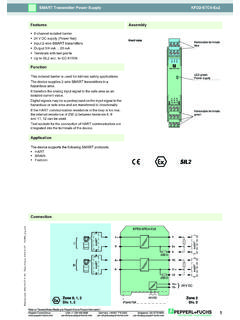
1 SMART Transmitter Power Supply KFD2-STC4 -Ex1. Features Assembly 1-channel isolated barrier 24 V DC Supply ( Power Rail). Front view Input 2-wire and 3-wire SMART transmitters and 2-wire Removable terminals blue SMART current sources Output 0/4 mA .. 20 mA. Terminals with test points 1 2 3. Up to SIL2 acc. to IEC 61508 4 5 6. KFD2-STC4 -Ex1. Function LED green: Power Supply This isolated barrier is used for intrinsic safety applications. PWR. The device supplies 2-wire and 3-wire SMART transmitters in a hazardous area, and can also be used with 2-wire SMART . current sources. It transfers the analog input signal to the safe area as an 7 8 9. 10 11 12. isolated current value. 13 14 15. Digital signals may be superimposed on the input signal in the Removable terminals hazardous or safe area and are transferred bi-directionally. green If the HART communication resistance in the loop is too low, the internal resistance of 250 between terminals 8 and 9.
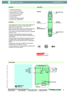
2 Can be used. Test sockets for the connection of HART communicators are integrated into the terminals of the device. Application The device supports the following SMART protocols: HART. BRAIN 2. Foxboro Connection KFD2-STC4 -Ex1. 1+ 7- HART. HART. 2- 8+. Date of issue 2014-12-01. mA. 3 9. 250 . 5- HART. Release date 2014-12-01 16:23. mA. 6+ 14+. 15- 24 V DC. Zone 0, 1, 2 24 V DC Zone 2. Div. 1, 2 Power Rail Div. 2. Refer to "General Notes Relating to Pepperl+ fuchs Product Information". Pepperl+ fuchs Group USA: +1 330 486 0002. Germany: +49 621 776 2222. Singapore: +65 6779 9091. 1. Technical data KFD2-STC4 -Ex1. General specifications Signal type Analog input Supply Connection Power Rail or terminals 14+, 15- Rated voltage UN 20 .. 35 V DC. Ripple within the Supply tolerance Power loss W. Power consumption W. Input Connection terminals 1+, 2-, 3 or 5-, 6+. Input signal 0/4.
3 20 mA. Voltage drop V at 20 mA (terminals 5, 6). Input resistance 64 terminals 2-, 3 ; 500 terminals 1+, 3 (250 load). Available voltage 16 V at 20 mA terminals 1+, 3. Output Connection terminals 7-, 8+, 9. Load 0 .. 800 . Output signal 0/4 .. 20 mA (overload > 25 mA). Ripple 50 A rms Transfer characteristics Deviation at 20 C (68 F), 0/4 .. 20 mA. 10 A incl. calibration, linearity, hysteresis, loads and fluctuations of Supply voltage Influence of ambient temperature A/K. Frequency range field side into the control side: bandwidth with Vpp signal 0 .. kHz (-3 dB). control side into the field side: bandwidth with Vpp signal .. kHz (-3 dB). Settling time 200 s Rise time/fall time 20 s Electrical isolation Output/ Power Supply functional insulation, rated insulation voltage 50 V AC. Directive conformity Electromagnetic compatibility Directive 2004/108/EC EN 61326-1:2006.
4 Conformity Electromagnetic compatibility NE 21:2006. Degree of protection IEC 60529:2001. Protection against electrical shock UL 61010-1:2012. Ambient conditions Ambient temperature -20 .. 60 C (-4 .. 140 F). Mechanical specifications Degree of protection IP20. Mass approx. 200 g Dimensions 20 x 124 x 115 mm ( x x in) , housing type B2. Mounting on 35 mm DIN mounting rail acc. to EN 60715:2001. Data for application in connection with Ex-areas EC-Type Examination Certificate BAS 99 ATEX 7060 , for additional certificates see Group, category, type of protection II (1)G [Ex ia Ga] IIC , II (1)D [Ex ia Da] IIIC. Input [Ex ia Ga] IIC, [Ex ia Da] IIIC. Supply Maximum safe voltage Um 250 V (Attention! The rated voltage can be lower.). Equipment terminals 1+, 3- Voltage Uo V. Date of issue 2014-12-01. Current Io mA. Power Po 551 mW. Equipment terminals 2-, 3. Current Io/Current Ii 74 mA / 115 mA.
5 Current Ii 115 mA. Voltage Uo V. Current Io 74 mA. Release date 2014-12-01 16:23. Power Po 64 mW. Equipment terminals 1+, 2 / 3- Voltage Ui 30 V. Current Ii 115 mA. Voltage Uo V. Current Io 115 mA. Refer to "General Notes Relating to Pepperl+ fuchs Product Information". Pepperl+ fuchs Group USA: +1 330 486 0002. Germany: +49 621 776 2222. Singapore: +65 6779 9091. 2. Technical data KFD2-STC4 -Ex1. Power Po 584 mW. Equipment terminals 5-, 6+. Voltage Ui 30 V. Current Ii 115 mA. Voltage Uo V. Current Io 0 mA. Output Maximum safe voltage Um 250 V (Attention! The rated voltage can be lower.). EC-Type Examination Certificate DMT 01 ATEX E 133. Group, category, type of protection I (M1) [Ex ia] I. Statement of conformity T V 99 ATEX 1499 X , observe statement of conformity Group, category, type of protection, II 3G Ex nA II T4 [device in zone 2]. temperature class Electrical isolation Input/Output safe electrical isolation acc.
6 To IEC/EN 60079-11, voltage peak value 375 V. Input/ Power Supply safe electrical isolation acc. to IEC/EN 60079-11, voltage peak value 375 V. Directive conformity Directive 94/9/EC EN 60079-0:2012 , EN 60079-11:2012 , EN 60079-15:2010 , EN 50303:2000. International approvals UL approval Control drawing 116-0173 (cULus). IECEx approval IECEx BAS Approved for [Ex ia Ga] IIC, [Ex ia Da] IIIC, [Ex ia Ma] I. General information Supplementary information EC-Type Examination Certificate, Statement of Conformity, Declaration of Conformity, Attestation of Conformity and instructions have to be observed where applicable. For information see Accessories Power feed module KFD2-EB2. The Power feed module is used to Supply the devices with 24 V DC via the Power Rail. The fuse-protected Power feed module can Supply up to 150 individual devices depending on the Power consumption of the devices.
7 Collective error messages received from the Power Rail activate a galvanically-isolated mechanical contact. Power Rail UPR-03. The Power Rail UPR-03 is a complete unit consisting of the electrical insert and an aluminium profile rail 35 mm x 15 mm. To make electrical contact, the devices are simply engaged. Profile Rail K-DUCT with Power Rail The profile rail K-DUCT is an aluminum profile rail with Power Rail insert and two integral cable ducts for system and field cables. Due to this assembly no additional cable guides are necessary. Power Rail and Profile Rail must not be fed via the device terminals of the individual devices! Date of issue 2014-12-01. Release date 2014-12-01 16:23. Refer to "General Notes Relating to Pepperl+ fuchs Product Information". Pepperl+ fuchs Group USA: +1 330 486 0002. Germany: +49 621 776 2222. Singapore: +65 6779 9091. 3.