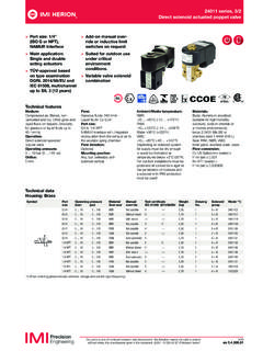
Transcription of SMC Pneumatics VT307 3-Port Direct Operated …
1 3 Port Solenoid ValveDirect Operated poppet TypeSeries VT307 Rubber SealT0 GHDET307015 DVTF0201 SZNTFVO307 (-Q)ManifoldJIS SymbolOptionCE-compliantQCE-compliant Electrical entry: D/DO,DZ/DOZ onlyCompact yet provides a large flow capacityDimensions (W x H x D) 30 x x 33(Grommet)C: dm3/(s bar){Rc 1/4 (Passage 2 3)}Low power consumptionVT/VO307 W DC/Standard typeVT/VO307Y) 2 W DC/Energy-saving typeVT/VO307 WSuitable for use in vacuum applications kPa(For vacuum specifications type: VT/VO307V, VT/VO307W)A single valve with 6 valve functions(Universal porting type)Selective porting can provide 6 valve functions, such as valve, valve, Divider valve, Selector valve, typeBody portedManifold OptionValve optionNilStandard typeE Y Energy-saving type(2 W DC)V For vacuumW Energy-saving type, For vacuum123 4 56 9 100 VAC, Hz200 VAC, Hz110 VAC, Hz220 VAC, Hz24 VDC12 VDC7 240 VAC, HzOther OptionRated voltage50605060506050605060 Electrical entryGGrommet, 300 mm lead wireHGrommet, 600 mm lead wireDDIN terminalEGrommet terminalTConduit terminalOption(6A)Without port (For manifold)18 Nil(8A)
2 14 Port sizeLight/Surge voltage suppressorSurge voltage suppressor mounting partNilNoneWith surge voltage suppressor(Grommet type is only available.)Refer to the figure light/surge voltage suppressor(Except grommet type)RcGNPTNPTFNil As for the case of rated voltage [Others (9)], please contact voltage suppressorNilContinuous duty typeModelApplicable manifold typeCommon or individual exhaustAccessoryFunction plate (DXT152-14-1A) Note)Mounting screw (NXT013-3)Note) It is not applied to Continuous duty type . Refer to the accessories on page (With thread)Thread typeHow to OrderFNilWith foot bracketWithout bracket1601 Note) Applicable only for DIN terminal type.[Option] 5:08 PM Page 1 Courtesy of Steven Engineering, Ryan Way, South San Francisco, CA 94080-6370-Main Office: (650) 588-9200-Outside Local Area: (800) [dm3/(s bar)]bCv1/81/4C [dm3/(s bar)]bCvC [dm3/(s bar)]bCvC [dm3/(s bar)] sure that dust and/or other foreign materials do not enter the valve from the unused port ( exhaust port).
3 Also, since there is a breathing port for the armature in the manual override part, do not allow accumulation of dust and/or other foreign materials to block bleed to Calculate the Flow RateFor obtaining the flow rate, refer to front matters 44 to SpecificationsFluidAmbient and fluid temperatureResponse timeLubricationManual overrideShock/Vibration resistance Enclosure(2)(1)Air 10 to 50 C (No freezing. Refer to page 5.)Type of actuationDirect Operated type 2 position single solenoidOperating pressure range0 to MPa20 ms or less (at the pressure of MPa)Not required (Use turbine oil Class 1 ISO VG32, if lubricated.)Max. operating frequency10 HzNon-locking push typeMounting orientationUnrestricted150/50 m/s2 Dustproof OptionNote 1) Based on dynamic performance test, JIS B 8374-1981.
4 (Coil temperature: 20 C, at rated voltage, without surge suppressor)Note 2) Impact resistance: No malfunction occurred when it is tested with a drop tester in the axial direction and at the right angles to the main valve and armature in both energized and de-energized states every once for each condition. (Values at the initial period)Vibration resistance: No malfunction occurred in a one-sweep test between 45 and 1000 Hz. Test was performed at both energized and de-energized states in the axial direction and at the right angles to the main valve and armature. (Values at the initial period)Note 3) At rated voltageNote 4)The value is different for continuous duty type (VT307E), and energy-saving type (VT307Y/W).
5 Refer to Option shown entryCoil rated voltage (V)Allowable voltage fluctuationApparent powerACDCACDCDCAC (50/60 Hz) InrushHoldingGrommet, Grommet terminal, Conduit terminal, DIN terminal100, 200, 110 , 220 , 240 24, 12 15 to +10% of rated VA (50 Hz) VA (60 Hz) VA (50 Hz) VA (60 Hz) Without indicator light: W, With indicator light: 5 WVaristor, Neon bulbDiode, LED (Neon bulb for 100 V or more)(3) (4)Power consumptionLight/Surge voltage suppressor(Not applicable for grommet type)(3) (4)MassGrommetPortsizeFlow kgFlow Characteristics/MassValve modelVT307VT307V (Vacuum spec. type)VT307E (Continuous duty type)VT307Y (Energy-saving type)VT307W (Energy-saving, Vacuum spec. type)VT307VT307V (Vacuum spec.)
6 Type)VT307E (Continuous duty type)VT307Y (Energy-saving type)VT307W (Energy-saving, Vacuum spec. type)Note) Values for a single valve unit. It differs in the manifold case. Refer to manifold specifications on page 2 (P A)2 3 (A R)3 2 (R A)2 1 (A P)CautionCautionIf low power consumption is required for electronic control, VY307Y(W) (2 W DC) is different from standard are as vacuum model has less air leakage than the standard model under low pressure. It is recommended for vacuum this valve has slight air leakage, it can not be used for vacuum holding (including positive pressure holding) in the pressure different from standard are as consumption/DC2 W, W (With indicator light) 25 ms or less (at MPa)Response time(1) 100 VDC: WNote 1) Refer to Note 1) of standard 2) For the flow characteristics, refer to Flow Characteristics.
7 Operating pressure range kPa to MPaContinuous duty type: VT307 EExclusive use of VT307E is recommended for continuous duty with long time (50 Hz) , (60 Hz) (50 Hz) , (60 Hz) Power consumption/DC2 W, W (With indicator light)30 ms or less (at the pressure of MPa)Response time(1)Note 1) Refer to Note 1) of standard 2) For the flow characteristics, refer to Flow Characteristics .OptionEnergy-saving type: VT307Y (VT307W)Vacuum spec. type: VT307V (VT307W) model is for continuous duty, not for high cycle rates. But even in low cycle rates, if energizing the valve more than once a day, please consult with solenoid should be done at least once in 30 different from standard are as sure to read before handling.
8 Refer to front matters 58 and 59 for Safety Instructions and pages 3 to 7 for 3/4/5 Port Solenoid Valve 4:01 PM Page 1602 Courtesy of Steven Engineering, Ryan Way, South San Francisco, CA 94080-6370-Main Office: (650) 588-9200-Outside Local Area: (800) principle<De-energized>Spool valve w is pushed upward by the return spring e, port P is closed, and then port A and port R are flow direction:Port P Block, A R<Energized>When an electric current is applied to the molded coil r, the armature t is attracted to the core y, and through the push rod u, it pushes down the spool valve w and port R is closed. Then, port P and port A are connected.
9 At this time, there will be gaps between the armature t and the core y, but the armature t will be magnetically attracted to the core flow direction:Port P Port A , Port R valveReturn springMaterialAluminum die-castedAluminum, NBRS tainless steelMolded coilResinNoteColor: Platinum silverComponent PartsHow to Use DIN Terminal1. Disassembly1)After loosening the thread (1), then if the housing (2) is pulled in the direction of the thread (1), the connector will be removed from the body of equipment (solenoid, etc.).2)Pull the thread (1) out of the housing (2).3)On the bottom part of the terminal block (3), there s a cut-off part (9). If a small flat head screwdriver is inserted between the opening in the bottom, terminal block (3) will be removed from the housing (2).
10 (Refer to Figure 1 .)4)Remove the cable gland (4) and plain washer (5) and rubber seal (6).2. Wiring1)Passing through the cable (7), cable gland (4), plain washer (5), rubber seal (6) in this order, and then insert into the housing (2).2)From the terminal block (3), loosen the screw (11), then pass the lead wire (10) through, then again tighten the screw (11).Note 1) Tighten within the tightening torque of N m 15%.Note 2) Cable (7) external: 6 to 8 mmNote 3) Crimped terminal like round-shape or Y shape cannot be Assembly 1) Passing cable gland (4), washer (5), rubber seal (6), housing (2) in this order through cable (7) and connect to terminal block (3) and then set the terminal block (3) to the housing (2).
