Transcription of SMD 0603, Glass Protected NTC Thermistors
1 BCcomponents Revision: 21-Sep-20211 Document Number: 29056 For technical questions, contact: DOCUMENT IS SUBJECT TO CHANGE WITHOUT NOTICE. THE PRODUCTS DESCRIBED HEREIN AND THIS DOCUMENTARE SUBJECT TO SPECIFIC DISCLAIMERS, SET FORTH AT 0603, Glass Protected NTC ThermistorsLINKS TO ADDITIONAL RESOURCESDESIGN-IN SUPPORTFor complete curve computation, please visit: APPROVALSA gency approval documents, please see: TCR ranging from -7 %/K at -40 C to -2 %/K at 150 C Tolerance on R25 down to 1 %, and on B25/85down to 1 % Suitable for wave or reflow soldering NiSn terminations Fully Glass coated and Protected cULus recognized, file E148885 (UL category XGPU2 / XGPU8) AEC-Q200 qualified Material categorization: for definitions of compliance please see Temperature sensing, protection and compensation in automotive, industrial, telecom and consumer applications.
2 Examples are:- Battery chargers-Power supplies- Office equipment- LCD compensation- In-car entertainmentDESCRIPTIONSize 0603 (M1608) Glass Protected SMD chip thermistor with negative temperature coefficient (TCR) and matte tin (Sn) plated terminations. The device has no AND WARNINGS ON MOUNTING AND HANDLINGP lease read the special instructions: see in 8 mm punched paper tape on reel package of 4000 (1)Replace * in SAP material number by J for 5 %, H for 3 %, G for 2 %, F for 1 % tolerance on R25 QUICK REFERENCE DATAPARAMETERVALUEUNITR esistance value at 25 C1K to 100K Tolerance on R25-value 1; 2; 3.
3 5%B25/85-value3170 to 4100 KTolerance on B25/85-value 1%Maximum dissipation at 25 C125mWThermal time constant 8sDissipation factor temperature range at zero power-40 to +150 CWeight ModelsDesign ToolsELECTRICAL DATA AND ORDERING INFORMATIONR25( )R25-TOL.( %)B25/85(K)B25/85-TOL.( %)UL MATERIAL AND ORDERING NUMBER (1)10003, 531701 NTCS0603E3102*LT15003, 532801 NTCS0603E3152*LT20001, 2, 3, 534201 NTCS0603E3202*LT22001, 2, 3, 535201 NTCS0603E3222*MT27001, 2, 3, 536001 NTCS0603E3272*MT47001, 2, 3, 538301 NTCS0603E3472*HT50001, 2, 3, 534801 NTCS0603E3502*LT10 0001, 2, 3, 534351 NTCS0603E3103*LT10 0001, 2, 3, 536101 NTCS0603E3103*MT10 0001, 2, 3, 539601 NTCS0603E3103*HT15 0001, 2, 3, 536001 NTCS0603E3153*MT22 0001, 2, 3, 537301 NTCS0603E3223*MT33 0001, 2, 3, 538601 NTCS0603E3333*HT47 0001, 2, 3, 539601 NTCS0603E3473*HT68 0001, 2, 3.
4 539851 NTCS0603E3683*HT100 0001, 2, 3, 541001 NTCS0603E3104* BCcomponents Revision: 21-Sep-20212 Document Number: 29056 For technical questions, contact: DOCUMENT IS SUBJECT TO CHANGE WITHOUT NOTICE. THE PRODUCTS DESCRIBED HEREIN AND THIS DOCUMENTARE SUBJECT TO SPECIFIC DISCLAIMERS, SET FORTH AT in millimetersSOLDERING CONDITIONSS oldering, handling, and mounting conditions are detailed in the instructions document: see examples of a soldering processes that will provide reliable joints without damage, are shown TAPE SPECIFICATIONSAll tape specifications are in accordance with IEC 60286-3.
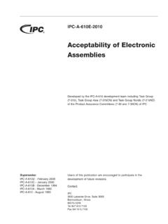
5 Basic dimensions are given below. Carrier tape material is TAPEN otes(1)Measured mm above base pocket(2)P0 pitch cumulative error over any 10 pitches mmTL1WL2L3L4L1 WTL2 AND (s)050100150200200250100150 Temperature ( C)500300250260 C 245 C215 C180 C130 C2 K/s40 s10 s10 sReflow SolderingLead (Pb)-free Reflow Soldering Profile 260 C 245 C235 C 170 C 120 C2 (s)050100150200350200250100150 Temperature ( C)50030040 s max. 60 s20 s limit 2503006 Recommended solder land pattern dimensions (mm) FWP0P2D0B0A0P1E1 JWB288TT1 DIMENSIONS OF PAPER TAPE in millimetersPARAMETERDIMENSIONA0 (1) (1) (2) tape thickness cover tape thickness Disclaimer Revision: 01-Jan-20221 Document Number: 91000 Disclaimer ALL PRODUCT, PRODUCT SPECIFICATIONS AND DATA ARE SUBJECT TO CHANGE WITHOUT NOTICE TO IMPROVE RELIABILITY, FUNCTION OR DESIGN OR OTHERWISE.
6 Vishay Intertechnology, Inc., its affiliates, agents, and employees, and all persons acting on its or their behalf (collectively, Vishay ), disclaim any and all liability for any errors, inaccuracies or incompleteness contained in any datasheet or in any other disclosure relating to any makes no warranty, representation or guarantee regarding the suitability of the products for any particular purpose or the continuing production of any product. To the maximum extent permitted by applicable law, Vishay disclaims (i) any and all liability arising out of the application or use of any product, (ii) any and all liability, including without limitation special, consequential or incidental damages, and (iii)
7 Any and all implied warranties, including warranties of fitness for particular purpose, non-infringement and regarding the suitability of products for certain types of applications are based on Vishay's knowledge of typical requirements that are often placed on Vishay products in generic applications. Such statements are not binding statements about the suitability of products for a particular application. It is the customer's responsibility to validate that a particular product with the properties described in the product specification is suitable for use in a particular application.
8 Parameters provided in datasheets and / or specifications may vary in different applications and performance may vary over time. All operating parameters, including typical parameters, must be validated for each customer application by the customer's technical experts. Product specifications do not expand or otherwise modify Vishay's terms and conditions of purchase, including but not limited to the warranty expressed included in this datasheet may direct users to third-party websites. These links are provided as a convenience and for informational purposes only.
9 Inclusion of these hyperlinks does not constitute an endorsement or an approval by Vishay of any of the products, services or opinions of the corporation, organization or individual associated with the third-party website. Vishay disclaims any and all liability and bears no responsibility for the accuracy, legality or content of the third-party website or for that of subsequent as expressly indicated in writing, Vishay products are not designed for use in medical, life-saving, or life-sustaining applications or for any other application in which the failure of the Vishay product could result in personal injury or death.
10 Customers using or selling Vishay products not expressly indicated for use in such applications do so at their own risk. Please contact authorized Vishay personnel to obtain written terms and conditions regarding products designed for such license, express or implied, by estoppel or otherwise, to any intellectual property rights is granted by this document or by any conduct of Vishay. Product names and markings noted herein may be trademarks of their respective owners. 2022 VISHAY INTERTECHNOLOGY, INC. ALL RIGHTS RESERVED