Transcription of SMD Rework Station - Official Hakko Distributor …
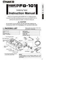
1 Thank you for purchasing the Hakko 850B SMD Hakko 850B is designed to solder and desolder surfacemounted devices with hot read this manual before operating the Hakko this manual readily accessible for reference. TABLE OF CONTENTSPACKING LIST / SPECIFICATIONS .. 1 SAFETY INSTRUCTIONS .. 2 PART NAMES .. 3 PREPARATION: ASSEMBLY AND ELECTRICAL CONNECTION .. 4 OPERATION .. 5 MAINTENANCE / INSPECTION .. 7 TEMPERATURE DISTRIBUTION CHART .. 8 OPTIONAL NOZZLES .. 11 PARTS LIST / HANDPIECE .. 12 Station .. 13 WIRING DIAGRAM .. 15 SMD Rework Station1 PACKING LISTC heck the contents of the Hakko 850B package andconfirm that all the items listed below are included: Hakko 850B Station .. 1 Power cord .. 1 Handpiece holder .. 1FP pick-up .. 1FP pick-up wire .. 1 Instruction manual .. 1* This product does not include a nozzle. A largeselection of nozzles is available for the Hakko850B. Select the nozzle or nozzles suitable for thework to be consumptionHakko 850B100V 280W 110V 270W 120V 300W220V 300W 230V 310W 240V 310W PowerConsumptionPumpCapacityControl temperature External dimensionsWeight30 W(Stand-by power consumption 100 120V 2W, 220 240V 4W)Diaphragm pump23 /min (max)100 420 C (212 788 F)(Use A1126B)225(l) 160(w) 145(h) (l) (w) (h) kg.
2 ( lb.) StationPowerconsumptionTotal length(w/o cord) Weight(w/o cord)100V 250W 110V 240W 120V 270W220V 270W 230V 280W 240V 280W 196(l) mm / (l) g / lb. Handpiece* This product is ESD-protected.* Specifications and design subject to change without 850B stationHandpiece holderHandpieceFP pick-upwith (S) wireFP pick-up wire (L)Power cord2 SAFETY INSTRUCTIONS WARNINGW arnings and cautions are placed at critical points in this manual to direct the operator's attentionto significant items. They are defined as follows: WARNING:Failure to comply with a WARNING may result in serious injury or death. CAUTION:Failure to comply with a CAUTION may result in injury to the operator, ordamage to the items involved. Two examples are given below. Be sure to comply with following WARNINGS and CAUTIONS for your safety. WARNING Be sure not to operate the unit with any combination of temperature and air flow settings thatmakes the thermal protector trip (the heater lamp turns off during use).
3 This could damage theunit. After use, do not disconnect the plug during the automatic cool-down process. CAUTIONWhen the power is ON, the temperature of the hot air and the nozzle ranges from 100 to450 C. (212 to 842 F.). To avoid injury to personnel or damage to items in the work area,observe the following: Do not direct the hot air toward personnel or touch the metal parts near the nozzle. Do not use the product near combustible gases or flammable materials. Advise those in the work area that the unit can reach very high temperatures and should beconsidered potentially dangerous. Turn the power OFF when no longer using the Hakko 850B or when leaving it unattended. Before replacing parts or storing the unit, allow the unit to cool and then turn the power OFF. To prevent accidents and failures, be sure to take the following precautions: Do not strike the handpiece against hard surfaces or otherwise subject it to physical shock.
4 Thiswill damage the quartz glass shield around the heating element, and could damage the heateras well. Be sure the unit is grounded. Always connect power to a grounded receptacle. Do not disassemble the pump. Do not modify the unit. Use only genuine Hakko replacement parts. Do not wet the unit or use the unit with wet hands. Remove power cord by holding the plug - not the wires. Make sure the work area is well ventilated. The Hakko 850B is not intended for use by children or infirm persons without supervision. Children should be supervised to ensure that they do not play with the Hakko CONTROLPOWERAIR CONTROL1234876512348765 CAUTIONHOTT emperature control knobAir flow control knobHandpiece holdermounting screwHandpiece holdermounting screwFuseHandpiece holderPower receptacleNozzle (not included)FP pick-up with (S) wire(Width of wire 14mm ( ))FP pick-up wire (L)(Width of wire 30mm ( ))Heater lampPower switchAir flow lampPART NAMES3 StationHandpieceAccessories3 CAUTIONHOTPREPARATION: ASSEMBLY AND ELECTRICAL CONNECTIONP reparation: Assembly and Electrical ConnectionA.
5 Station Assembly Attach the handpiece the handpiece holder mountingscrew from the side of the Station . Attach thehandpiece holder to the Station . (Figure 1)(The handpiece holder can be installed oneither the left or right side.)B. Handpiece Assembly Attach the the nozzle mounting screw. Attachthe nozzle as shown in the drawing.(Figure 2)C. Electrical Connection andPower ON1. Connect the power cord to the powerreceptacle on the back panel of thestation. (Figure 4)2. Place the handpiece on the holder.(Figure 5)3. Plug the power cord into a grounded wallsocket. After connection, the automaticblowing function will start sending airthrough the pipe, but the heating elementremains Turn the power switch :The power switch may be turned on atany time while the automatic blowingfunction is operating. Once the powerswitch is turned on, the heating elementwill begin to warm the nozzlemounting screw.
6 (Figure 1)(Figure 2)(Figure 3)Inside screw(Figure 4)When installing an optionalnozzle to the Hakko 850B, donot remove this inside product is ESD-protected. Be sure to use a grounded View(Figure 5)CAUTIONWhen not in use, place the handpieceon the CONTROLPOWERAIR CONTROL1234876512348765 Temperature control knobAir flow control knobOPERATION QFP Desoldering1. Adjust the air flow and temperaturecontrol to the temperature distribution chart(page 8) to adjust the air flow and temper-ature control knobs. Wait for the temper-ature to stabilize for a short period of the thermal protector is tripped (the heaterlamp turns off during use), reduce the tem-perature setting or increase the air flow. Be surenot to operate the unit with temperature and airflow settings that makes the thermal protectortrip. This could damage the Place the FP pick-up under the IC the FP pick-up wire under the IC lead.
7 (Refer to the photo shown.)If the width of the IC does not match thesize of the FP pick-up, adjust the width ofthe pick-up by squeezing the wire. In caseof PLCC or small components such aschip resistors, desolder by usingtweezers, HeatingHold the handpiece so that the nozzle islocated directly over, but not touching theIC, and allow the hot air to melt the careful not to touch the leads of the ICwith the Remove the the solder has melted, remove theIC by lifting the FP Remove any remaining removing the IC, remove remainingsolder with a soldering iron and wick ordesoldering QFP the solder the proper quality of solder pasteand install the SMD on the the to the photo to preheat the lead frame soldering is completed, clean theresidual flux from the board with anappropriate :Soldering with hot air has many advantages,such as the inherent ability to pre-heat thecomponent being replaced.
8 As with anysoldering process, however, there is always thepossibility of forming solder balls, bridgesbetween leads, and inadequate solder inspect the finished solder joints forstructural and electrical integrity. Turn the power switch the power switch is turned off, anautomatic blowing function begins sendingcool air through the pipe in order to cool thehandpiece. Do not disconnect the plugduring this cooling the cooling process, the amount of air iscontrolled by the setting of the air flow adjustmentknob. Hakko recommends setting the knob at 8when cooling for greatest / INSPECTION Broken heating elementA. Open the handpiece1. Remove the three screws holding thehandpiece together. (Figure 1)2. Move the tube away from the handpiece,as Open the handpiece. Disconnect thegrounding wire sleeve (1) and pipe fromthe protruding portion of the the glass and heat insulation are inside thepipe.
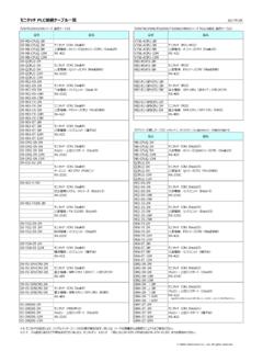
9 Be careful not to drop or lose these Disconnect the connector (2) and removethe heating Measure the resistancevalueConnect an ohmmeter across the connectorterminals (a). The correct values are approxi-mately:26-40 (100-120V), 70-100 (220-240V).If the resistance value is incorrect, replacethe part.(Refer to the instructions included with thereplacement part.)CAUTIONH andle the heating element with care. Never rubthe heating element wire!Insert the handle's projection into the hole in thepipe. Replacing the fuse1. Unplug the power cord from the Remove the fuse Replace the (100-120V), (220-240V)4. Put the fuse holder back in place.(Figure 1)Connector (2)Grounding wiresleeve (1)(a)7 TEMPERATURE DISTRIBUTION CHARTCAUTION These charts are for reference. If the thermal protector trips, reduce the temperature settingor increase the air : Air-flow and temperature adjustment of the Hakko 850 BThe temperature distribution chart relating air-flow and temperature settings for different nozzle typesprovided with the Hakko 850 are not to be used with the 850B.
10 The 850B uses a different pump and controlsystem and the flow-rates and temperature do not refer to the temperature distribution chart in the 850B instruction manual before criteria: Measured at a point 3mm ( in.) from the nozzle by Single ( )Air flowTemperature Control KnobAir Temperature C1246815842736 Temperature Control Knob15842736 Temperature Control Knob15842736 Temperature Control Knob15842736 Temperature Control Knob15842736 Temperature Control Knob15842736 Temperature Control Knob15842736500(932 F)300(572 F)100(212 F)Air Temperature C500(932 F)300(572 F)100(212 F)Air Temperature C500(932 F)300(572 F)100(212 F)Air Temperature C500(932 F)300(572 F)100(212 F)Air Temperature C500(932 F)300(572 F)100(212 F)Air Temperature C500(932 F)300(572 F)100(212 F)Air Temperature C500(932 F)300(572 F)100(212 F)Air Temperature C500(932 F)300(572 F)100(212 F)Air Temperature C500(932 F)300(572 F)100(212 F)Air flow2468A1125 BQFP 10 10 ( )Air flow2468A1126 BQFP 14 14 ( )Air flow2468A1129 BQFP 28 28 ( )Air flow2468A1128 BQFP 14 20 ( )Air flow2468A1127 BQFP ( )