Transcription of SNN SPLIT PLUMMER BLOCKS - bearing
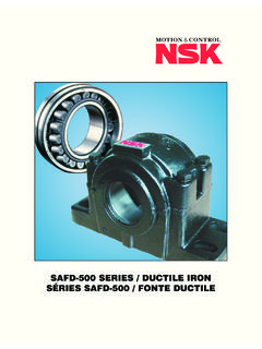
1 SNN SPLIT PLUMMER BLOCKS 2 SNN SPLIT PLUMMER BLOCKSFROM NSKThe SNN SPLIT PLUMMER block from NSK combines quality materials and design tomaximize bearing performance. With features like serialized cap and base to preventmixing of components, alignment aids, two and four-bolt mounting and multiple positioningof grease fittings, this housing replaces all others in the SN family. Additional featuresinclude:Precision machined bearing seat Web design for efficient heat transfer Solid cornersfor locating pins ISO grade cap bolts Square-shaped base with center marks foralignment Designed for either grease or oil lubrication with a large oil reservoir 3 FEATURES AND BENEFITSHigh-grade boltsISO forpositioning pinsSquare-shaped baseFacilitates alignmentHigh-precision boreMaximizes bearing performanceSeal Groove forvarious types of sealsSplit seal, V-ring seal.
2 Labyrinth sealThreaded hole for grease nipplePlug for threaded hole is standardDimples for additional holesThese can be utilized for sensors orlubrication holes for the seal or bearingCap and base are serializedDimples forfour boltmountingIdeally shapedstiffer designLarge oil bathProlongs oil change intervalIdeal casting designHigh strength, rigid andlightweightFree surfaceAllows for drain holeWebs for heat transferRib for bearing seatPrevents deformation of bearing seatCenter marksFacilitates alignmentRibs to minimize deformationcaused by tightening themounting boltsSolid corners forlocating pins 4 HOUSING TO ORDERCONTACTNON-CONTACTEND COVERG-LOK SEALV-RING SEALTS-RING SEALAXXXMax.
3 Speed5 m/s7 m/s-Grease LubricationExcellentExcellentGood-Oil LubricationFairGoodExcellent-Friction torqueGoodGoodExcellent-Temperature range-20 thru +80 C-20 thru +80 C-20 thru +120 C-20 thru +120 CDustExcellentExcellentGood-PerformanceL arge particlesGoodPoorGood-WaterGoodGoodPoor- SEAL TYPES AND THEIR FEATURESSNN518615 The SNN series comprises a number of housings which, when combined with different seal options and ball orspherical roller bearings, provides an answer for most PLUMMER block applications with shaft diameters rangingfrom 3/4" to " (20mm to 140mm). bearing bore codeHeavy series housingBearing bore codeMedium series housingHousing design codeWhen ordering a complete assembly, you will receive the following components ( ):1 - SNN517 housing1 - G517 double-lip seal for a " shaft1 - 22217 EAKE4 spherical roller bearing1 - HA317 adapter sleeveIf the assembly is to be fixed, add the letter X to the assembly part number, , youwill receive 2 fixing rings You must specify the number of fixed assemblies at time of.
4 Only one assembly per shaft should be one side of the housing will be closed, add the letter Y to the assembly part number, You will receive one end cover A517. 5 The inner rings of tapered bore spherical rollerbearings are always mounted with an interference farther the bearing is pushed up the taper, thegreater the degree of interference and the greater thereduction of internal radial clearance within thebearing. It is necessary to measure this reduction asyou mount the bearing to the shaft in order to have aproperly functioning bearing . Use the following steps:1Do not start this procedure until you are ready tomount the bearing .
5 If the mounting process isinterrupted, cover the bearing and workspace toprevent with a clean workspace ensuring that benchand tools are free from dirt, dust or the bearing from its container and innerwrap, standing the bearing upright on the the inner ring of the bearing slowly for onerevolution so that the rolling elements alignthemselves with the raceways. Make sure theinner ring is parallel with the outer to Table 1, select as a starting point afeeler gauge in the mid-range of the bearings unmounted the top set of rollers, work the feeler gaugebetween the roller and the outer raceway.
6 Thecorrect gauge will create a slight that the gauge is being worked over bothof the top rollers of each raceway for a correctreading. Your reading should be within the valuesin Table a reading at the high end, use the maximumreduction value from Table 2. For a reading at thelower end, use the lower value from Table the value you determine from Table 2from Table 1. This is the final or residual clearanceand cannot be less than the minimum residualclearance shown in Table 2. Write down what yourfinal clearance should be after the bearing and adapter sleeve on theshaft and tighten the lock nut, measuring theinternal clearance at regular intervals, until thefinal clearance is reached.
7 With the bearingsuspended on the shaft, the clearance readingsare taken at the bottom rather than the the lock washer tab in place. If necessary,continue to tighten the lock nut to align the washertab and slot. Do not back off the lock nut toachieve Bore Clearance Tapered BoreReduction in RadialAxial Movement (1)Minimum PermissibleCNC3C4 ClearanceTaper 1 : 12 Residual ShaftDiameterMax. PermissibleDiameterTolerancesTaper and +.000 +.000 +.000 +.000 +.
8 000 +.000 ADJUSTMENT FOR SPHERICAL ROLLER BEARINGSWITH TAPERED BORE(1)Valid for solid steel shafts onlySHAFT TOLERANCE LIMITS FOR ADAPTER MOUNTTa b l e 1Ta b l e 2Ta b l e 3 Imperial shaft tolerances for bearings with adapter mount are shownin table 3. These values may be converted to millimeters for metricsizes. For conversion to millimeters multiply by 6 1 Remove the top half of the bearing housing toexpose the bearing the housing base in position and handtighten the fixing G-LOK kit includes four halves (2 Seals). Fitthe halves into the seal grooves machined in thebase and top of the housing.
9 To aid thelubrication of the running lips and sealingproperties of the G-LOK, fill the u-section of theseal with the bearing on the shaft and fill the shaft and bearing assembly on thelower half of the SPLIT the assembly that locates the system, fit thelocating rings on either side of the only one is supplied fit it on the same sideas the tapered sleeve lock the housings for alignment with eachother, ensuring that they are within acceptablelimits and that the fixing bolts are tightenedsufficiently to secure the top half of the housing should be carefullyaligned with the locating dowel pins and the boltstightened.
10 Be sure that the SPLIT housing is pairedonly with its original top half, as these parts arenot interchangeable from one housing fixing bolts can then be fully THE SNN SPLIT HOUSING USING G-LOK SEALS 7 1 Remove the top half of the bearing housing toexpose the bearing the housing base in position and handtighten the fixing a V-RING and counterface washer on theshaft. The counterface washer should bepositioned to align with the seal groovemachined in the housing and the the bearing on the shaft and charge the second V-RING and the counterfacewasher on the shaft and bearing assembly with the sealingcomponents can then be lowered into the baseof the housing, taking care to locate the rubberlip of the counterface washer in the SPLIT housingseal the assembly that locates the system, fit thelocating rings on either side of the only one is supplied fit it on the same sideas the tapered sleeve lock the housings for alignment with eachother.