Transcription of Snubbers & Restraints Metric - PIPE SUPPORTS …
1 Snubbers & Restraints MetriccontentsIntroduction ..1overview ..3snubbers (kgf) ..7 rigid struts (kgf) ..8 Welding clevis (kgf) ..9clamps (kgf) ..10 Riser clamps (kgf) ..40spreader Beams (kgf) ..63stiffness and Permissable Loads graphs (kgf) ..64snubbers (kn) ..65 rigid struts (kn) ..66 Welding clevis (kn) ..67clamps (kn) ..68 Riser clamps (kn) ..98spreader Beams (kn) ..121stiffness and Permissable Loads graphs (kn) ..122 Global Locations ..123 DYNAMIC RESTRAINTSIn pipework systems that are subject to dynamic loading, it may be necessary to use rigid struts, which act in both directions, rather than hanger rods, which only support downward acting struts are also used to provide lateral restraint where this is required. Snubbers are used where dynamic restraint is required, but the pipe has to be allowed to move RESTRAINTSI ntroductionAt Bergen pipe SUPPORTS we continually strive to meet the needs of our customers and the latest development in our range of hydraulic Snubbers brings about some significant benefits.
2 With over 40 years experience of manufacturing hydraulic Snubbers contributing to the evolution of this new model we are able to offer a world-class product to our global new hydraulic snubber is presented in a compact, symmetrical envelope with an integral, pressurised fluid reservoir that means they can be installed in any orientation. The use of corrosion resistant materials means that snubber bodies no longer need to be painted and installation in harsh environments is less of a concern than integrating the fluid reservoir within the length of the main cylinder we have considerably reduced the overall length of the snubber and the redefined range of sizes means that this unit will fit within the same space as some of our main competitors units. We offer nine cylinder sizes giving load capacities of up to 1000kN with strokes of up to features of the SNC range of Snubbers are compact, robust and corrosion resistant Internal, pressurised fluid reservoir Interchangeable with other manufacturers units Maintenance free, precision rod-end bearings Satisfies the key performance requirements of Annex D, BSEN13480-3 and MSS RESTRAINTS2-3-2-10123-1200-800-400040080 0120001 Load (kN)Displacement (mm)Time (seconds)-500-400-300-200-10010002003004 00500600-3-2-10123 Displacement (mm)Load (kN)
3 LoCk-Up ChARACTERISTICSCYCLIC TEST oN A 1000kN snubber AT 5hzDYNAMIC RESTRAINTS3overview10 Direction of loadingpipework systems which are subject to purely static loading are generally supported on single acting vertical SUPPORTS such as a hanger rod and pipe clamp, sliding base or other rigid type of the piping is subject to change in temperature then some or all of these vertical SUPPORTS may be spring SUPPORTS , either variable or constant effort type. Dynamic restraint of the pipework should a generally cannot be provided by the same system that carries the dead-weight of the loading may occur for a number of reasons. Un-steady flow, such as that caused by valve closure, produces dynamic forces and is referred to as water hammer. In an earthquake, a piping system is also subject to dynamic the pipework system is subject to dynamic forces, vibration of the pipework will occur.
4 This may be injurious to the pipework, connected equipment and plant. pipework systems which are supported on single acting vertical Restraints and springs with no lateral restraint will have low natural frequencies of vibration and will experience large dynamic deflections when subject to vibration; this will generally be unacceptable. pipework stress analysis either by response spectrum or time history analysis can be used to show the need for dynamic pipework systems which are subject to dynamic loading, it may be necessary to use rigid struts which act in both directions, rather than hanger rods, which only support downward acting loads. rigid struts are also used to provide lateral restraint where this is required. Snubbers are used where dynamic restraint is required, but the pipe has to be allowed to move STRUT FIGURE STRpipe SUPPORTS group manufacture a comprehensive range of rigid struts covering loading up to more than 90 tonnes with lengths up to 6 metres (12 8 ).
5 The struts are designed for ease of use and to provide a cost-effective dynamic restraint. rigid struts use spherical bearings to permit angulation and they provide length adjustment of +/- 100mm (4 ) by means of right and left hand threaded rod ends so that the adjustment can be made without disconnection. Maximum loadings are tabulated in kilograms, Newtons and pounds and weights and axial stiffnesses are also given. Having selected the size of strut that you need, the number-ing system used makes the selection of the associated welding clevis and clamp a simple CLEVIS FIGURE WCLThe welding clevis provides means of attachment of rigid struts and Snubbers to steelwork. The welding clevis is de-signed to provide +/- 5 degrees of lateral angulation across the pin connection and +/- 90 degrees of angulation around the pin connection as shown FIGURE SNCpipe SUPPORTS group s range of hydraulic Snubbers cover loadings up to more than 90 tonnes with cylinder stroke up to 300mm (12 ).
6 The part numbering system and sizes of end fittings are compatible with the other dynamic restraint components. Where it is necessary to extend the snubber to suit particular installation constraints we provide the snubber extension tube Figure SNE which provides overall pin-to-pin length adjustment of +/- 50 mm. The Figure SNc snubber is not provided with length adjustment, fine setting is done by simply adjusting the set position of the piston rod by extending or retracting it. Such adjustment should be limited to +/- hydraulic snubber is a standard 3000 psi hydraulic cylinder with a built-in fluid reservoir. The fluid is ported via the end block to the concentric reservoir. The reservoir acts as a compensator for volume variance & provides long-term fluid replenishment for the small, essential consumption of fluid necessary to lubricate the bearings & operation, normal thermal expansion of the pipework causes the piston rod to extend or retract at a velocity less than the lock-up velocity.
7 In this situation the snubber is inactive and the device has minimal effect on the behaviour of the pipework. In a dynamic situation, shock or vibration forces which cause the rate of displacement of the piston to exceed the lock-up velocity will cause the regulating valves to close and the snubber limits the velocity. The resistive capacity of the unit transfers the force to the structure and reduces the possibility of overstressing the pipe or associ-ated equipment the snubber is locked there is a by-pass path through which the fluid can pass at a very low rate. This is essential to allow the pipe to contract as it cools should the plant be shut-down during a seismic event. Where resistance to prolonged thrust is required such as around pressure relief valves, the by-pass is eliminated & the snubber transforms into a rigid restraint once it has been activated.
8 When the force decays the valves open & the snubber once again becomes RESTRAINTS4 CLAMpS FoR rigid STRUTS AND Snubbers FIGURES 521, 522, 523 & 524 pipe SUPPORTS group offer a very comprehensive range of clamps for rigid struts and Snubbers . The Figure 521 & 522 clamps are both single plate stiff clamps incorporating a sheathed U-bolt or pair of U-bolts. The Figure 523 & 524 clamps are both double-plate stiff clamps, again incorporat-ing a single or double sheathed U-bolt and having the axis of the connecting pin parallel to the axis of the four types of clamps use close tolerance load pins and are designed to operate within a 10 (degree) cone of load clamps are designed in four temperature ranges to suit maximum design temperatures of 400 c (752 F), 490 c (914 F), 530 c (986 F), and 570 c (1058 F). Maximum load-ings and pin sizes are compatible with those for the struts and CLAMp FoR rigid STRUTS AND Snubbers FIGURE 525In situations where it is necessary to restrain the pipe in its axis using a pair of struts or Snubbers the Figure 525 Tandem/Riser clamp should be used.
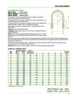
9 This is available to suit four temperature ranges like the stiff-clamps. SELECTIoN rigid STRUTSR igid struts are selected on the basis of maximum applied load and length between pin centres. The loading shown in the table is the maximum applicable for the size of strut in question. A reduced safe working load is shown for sizes c to J at a corresponding increased length. Between the normal maximum length & the increased maximum length linear interpolation shall be applied to derive the actual safe working example. Selection is STR-D with pin-to-pin length l of working load at 3000mm is 46kNSafe working load at 4000mm is 27kNSafe working load at 3500mm is calculated as 46 {(46-27)/1000 x 500}Therefore safe working load at 3500mm is not specify strut sizes where the length exceeds that given in the table. If a minimum stiffness of rigid strut is required, make reference to the tabulation of stiffness.
10 The lengths of rigid struts should be such that the maximum angulation is not exceeded, the attachment can be offset on installation if necessary to help achieve SNUbbERSD etermine the minimum required stroke by taking the antici-pated design movement and adding an allowance for excess travel. This allowance should normally be at least 20% of the anticipated design movement but not less than 25mm. Then select a snubber where the cylinder stroke is greater than or equal to the minimum required stroke and the applied loadings in tension and compression are less than the allow-able maximum loadings in tension and compression for the size and length of snubber as shown in the catalogue. For intermediate lengths, allowable compressive loadings may be determined by interpolation. The length of the snubber must be such that the maximum angulation is not exceeded.