Transcription of Soft Start-up Valve AV2000/3000/4000/5000 - SMC ETech
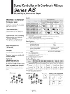
1 NewSoft Start-up ValveAV2000/ 3000 / 4000 / 5000 Large effective area (mm ) av2000 / 20 (Body size: 1/4)AV3000/ 37 (Body size: 3/8)AV4000/ 61 (Body size: 1/2)AV5000/113 (Body size: 3/4)AV5000/122 (Body size: 1 )Low power consumptionManual supply/exhaust combinationsModular with combinationsAC2000AC2500AC3000 combinationSoft Start-up Valve Except AC4000-06 Series AV5000introduced! combinationSoft BA Start-up Valve that gradually increases supply pressure during start up and rapidly exhausts system air when the supply air is shut off1T V approved productT V RheinlandBAUARTGEPR FTTYPEAPPROVEDAV001 GHow to OrderBody size203040501/43/81/23/4, 1 Electrical entryRated coil voltage1234569100 VAC (50/60Hz)200 VAC (50/60Hz)110 to 120 VAC (50/60Hz)220 VAC (50/60Hz)24 VDC12 VDCO therThread typeNilFNRcGNPTCM anual overrideNil: Non-lockingpush type(flush type)B: Locking type(tool required)2002 FSoft Start-up valvePort size02030406101/4 ( av2000 only)3/8 (AV3000 only)1/2 (AV4000 only)3/4 (AV5000 only) 1 (AV5000 only)OptionNilGNoneWith pressure gaugeC.
2 Locking type(lever type)Indicator light/Surge voltage suppressorNilSZNoneWith surge voltage suppressor (grommet type only)With indicator light/surge voltage suppressor(not possible with grommet type)SF4 How to Order Pilot Valve Assemblies1G80 Forsoft Start-up valveRated coil voltage1* 2*3*4*569100 VAC (50/60Hz)200 VAC (50/60Hz)110 to 120 VAC (50/60Hz)220 VAC (50/60Hz)24 VDC12 VDCO therElectrical entryGDYG rommetType D DIN terminalType Y DIN terminalIndicator lightSurge voltage suppressorNilSZNoneWith surge voltage suppressor(grommet type only)With indicator light/surge voltage suppressor(not possible with grommet type)Manual overrideNilBCNon-locking push type (flush type)Locking type (tool required)Locking type (lever type)D: Type D DIN terminalY: Type Y DIN terminalNote) The grommet type can have a surge voltage suppressor (direct coupling type lead wire), but without indicator to standards necessary to satisfy EC AV has received approval from T V Rheinland, an EC Notified Body (EC authorization number 0197), for conformity to DIN VDE0580: 1994 SMC for details when ordering T V approved products because of restrictions regarding product model, voltage specification, and electrical entry, SMC for other voltages (9).
3 *DIN Type onlyQQNilENJapan, Asia, AustraliaEuropeNorth AmeriaEOrdering source area codeSoft Start-up ValveAV2000/ 3000 / 4000 / 5000 ModelPort sizeProof pressureOperating pressure rangePressure gauge port sizeAmbient and fluid temperatureEffective area(mm )Weight (kg)Rated coil voltageAllowable voltage fluctuationCoil insulation typeApparent power(currentconsumption)Current consumption DCElectrical entryOptional specificationPilot Valve manual overrideAV20001 , 200, 110 to 120, 220 VAC (50/60Hz), 12, 24 VDC 15% to +10% of rated voltageEquivalent to B type (130 C) (50Hz), (60Hz) ( )/50Hz, ( ) D DIN terminal, Type Y DIN terminalIndicator light/Surge voltage suppressor Note 2)Non-locking push type (flush type),Locking type (tool required), Locking type (lever type)AV40001 pressure MPaNeedle Valve flow characteristicsAir flow l/min (ANR)Conditions: Primary pressure rotationsDescriptionPart rangePressure gaugeG36-10-011 MPaSpecifications3/41 Electrical specificationsInrushEnergized1(P) 2(A)2(A) 3(R)Piston B switching pressure (Open Closed) pressure MPa012345 Accessories/Pressure gaugeSymbol1(P)2(A)3(R) to 1 MPa1/80 to 60 C Note 1)AV4000AV5000AV3000AV2000 Type Y DIN terminalType D DIN terminalNote 1) Use dry air when operating at a low 2) The grommet type can have a surge voltage suppressor (direct coupling type lead wire), but without indicator 2 Soft Start-up Valve av2000 / 3000 / 4000 / 5000 Working PrincipleWorkingconditionLow speed supplyPilot valveONInitial operation return strokeCylinder drive circuit (meter-out control) exampleONOFF1(P)2(A)3(R)BBWorking descriptionPressure time chart (meter-out control)
4 ExamplePressureconditionsQuick exhaustNormaloperationHigh speedsupplyOFFBDCATimePressure strokeCylinder movement with fixed orificePR (atmospheric pressure)PA PP1(P)3(R)PAPP1(P)3(R)PAPP1(P)3(R)PAACD2 121211/2 PP > PABBPPB-B1/2 PP PA1/2 PP = approx. PA2(A)2(A)2(A)Since piston B holds the fully open condition, during normal operation the cylinder's speed will be controlled by the usual meter-out pilot Valve is turned OFF, spring pushes piston A and main Valve upward and opens R port while shutting off the air supply from P port. The pressure difference generated at this time opens check Valve and the residual pressure on the A port side is quickly exhausted from R port. When 1/2 PP PA after the cylinder rea-ches , piston B fully opens and PA in-creases rapidly as shown from to and becomes the same pressure as pilot Valve is turned ON by ener -gization or manual override, the pilot air pushes piston A and main Valve downward and opens main Valve while R port closes simultaneously.
5 The air from P port moves to needle Valve , where its flow is adjusted, and flows to A port. The meter-in control of needle Valve slowly moves the cylinder from to .3AV2000/ 3000 / 4000 partsPilot Valve assemblyPiston A assemblyPiston B assemblyMain Valve assemblyCheck valvePiston guide assemblyNeedle assemblyValve springPiston springCheck springNeedle springC type snap ring for shaftC type snap ring for holeSealSealO-ringPOM, NBRB rass, NBR (HNBR)Brass, NBR (HNBR)Brass, NBR (HNBR)POM, NBRB rass, NBRS teel wireStainless steelStainless steelSteel wireTool steelTool steelNBRNBRNBRAV2000P424204AP424205AP424 206AP424207P424208AP424209AP424211P42421 2P424213P424214G-50-9P424210P42421810 x 8 x 1AV3000P424304AP424305AP424306AP424307P4 24308AP424309AP424311P424312P424313P4243 14 STW-50-10P424310P42431511 x 9 x x x Refer to page 1 for pilot Valve assembly part number listDescriptionConstructionON OFF1(P)2(A)BB3(R)
6 45678910111213141516171819 MaterialAV5000P424504AP424505AP424506AP4 24507P424508AP424509AP424511P424512P4245 13 x x -80 Soft Start-up ValveAV2000/ 3000 / 4000 /50004 DIN terminal: AV 00- - D, DZDIN terminal for European use: AV 00- - Y, YZWith indicator light/surge voltage suppressorAV2000- 02- G av2000 - 02- GS av2000 - 02- D av2000 - 02- DZ av2000 - 02- Y av2000 - 02- YZ AV3000- 03- G AV3000- 03- GS AV3000- 03- D AV3000- 03- DZ AV3000- 03- Y AV3000- 03- YZ AV4000- 04- G AV4000- 04- GS AV4000- 04- D AV4000- 04- DZ AV4000- 04- Y AV4000- 04- YZ AV5000- - G AV5000- - GS AV5000- - D AV5000- - DZ AV5000- - Y AV5000- - YZ 1/41/41/43/83/83/81/21/21/23/4, 13/4, 13/4, 1 66 66 66 76 76 76 98 98 74 DimensionsSMCMADE IN JAPANOFFONLKAMGA pplicable heavy duty cord : 6, 8 Manual override (locking lever type)PARDBCQHI ndicator 37 ModelPortsizeABCDEGH IPressuregaugemountingbore 1/8 90 94 107 111 6 23 16 6 93 100 115 143 37 37 46 46 46 M4 x x 1 Depth 6M6 x 1 Depth x 1 Depth x 1 Depth x 1 Depth 6M6 x 1 Depth 6M5 x 5M5 x 5M5 x 5M4 x x +-0610061006100610061006105-96AV2000/300 0/ 4000 / 5000 Modular Combination SpacerSelect one of the spacers below when connecting to an combination unit (AC2000 to AC6000).
7 (Spacers must be ordered separately.)Y200-AY300-AY400-AY600-AAV20 00AV3000AV4000AV5000 Applicable modelModelSpacerSpacer with bracket Y200T-AY300T-AY400T-AY600T-AAV2000AV3000 AV4000AV5000 Applicable modelModelh bracket Y200T-AY400T-AY200-AY400-A5-97 Soft Start-up Valve av2000 / 3000 / 4000 / 5000 Series av2000 / 3000 / 4000 / 5000 Caution: Operator error could result in injury or equipment : Operator error could result in serious injury or loss of : In extreme conditions, there is a possible result of serious injury or loss of life. Safety InstructionsThese safety instructions are intended to prevent a hazardous situation and /or equipment damage. These instructions indicate the level of potential hazard by a label of "Caution", "Warning" or "Danger". To ensure safety, be sure to observe ISO 4414 Note 1), JIS B 8370 Note 2) and other safety The compatibility of pneumatic equipment is the responsibility of the person who designs the pneumatic system or decides its the products specified here are used in various operating conditions, their compatibility for the specific pneumatic system must be based on specifications or after analysis and/or tests to meet your specific requirements.
8 2. Only trained personnel should operate pneumatically operated machinery and air can be dangerous if an operator is unfamiliar with it. Assembly, handling or repair of pneumatic systems should be performed by trained and experienced Do not service machinery/equipment or attempt to remove components until safety is Inspection and maintenance of machinery/equipment should only be performed after confirmation of safe locked-out control When equipment is to be removed, confirm the safety process as mentioned above. Cut the supply pressure for this equipment and exhaust all residual compressed air in the Before machinery/equipment is restarted, take measures to prevent shooting-out of cylinder piston rod, etc. (Bleed air into the system gradually to create back pressure.)4. Contact SMC if the product is to be used in any of the following conditions:1. Conditions and environments beyond the given specifications, or if product is used Installation on equipment in conjunction with atomic energy, railway, air navigation, vehicles, medical equipment, food and beverages, recreation equipment, emergency stop circuits, press applications, or safety An application which has the possibility of having negative effects on people, property, or animals, requiring special safety 1) ISO 4414 : Pneumatic fluid power -- Recommendations for the application of equipment to transmission andcontrol 2) JIS B 8370.
9 General Rules for Pneumatic Actuator driveWhen a component such as a solenoid Valve or actuator is to be driven using this product, take appropriate measures to pre -vent potential danger caused by actuator Holding of pressureSince the products are subject to air leakage (allowed), they cannot be used for applications such as holding pressure in a pressure Maintenance spaceThe installation should allow sufficient space for maintenance Leakage voltageParticularly when using a C-R element (surge voltage suppres-sor) for protection of the switching element, take note that lea -kage voltage will increase due to leakage current flowing through the C-R element, Low temperature operationAlthough the Valve can be operated at a temperature as low as 0 C, measures should be taken to avoid solidification or free -zing of drainage and moisture, coil is 20% or less of rated coil is 3% or less of rated elementResistorOFFL eakage currentValvePower supply1.
10 Confirm the products presented in this catalog are designed only for use in compressed air systems. Do not operate at pressures or temperatures, etc., beyond the range of specifications, as this can cause damage or malfunction.(Refer to specifications.)Contact SMC when using a fluid other than compressed Extended periods of continuous energizationContact SMC if valves will be continuously energized for extended periods of Operation of closed centre solenoid valvesWhen closed center solenoid valves are used, or when used on an actuator with a load factor of 50% or more, jumping (lurching) cannot be prevented even if this product is Using a regulator on the secondary sideWhen mounting a regulator on the secondary side (A port side), use a residual pressure relief regulator (AR2550 to 4050) or a check type regulator (AR2560 to 6060).With a standard regulator (AR1000 to 6000), the secondary side pressure may not be released when this Valve is Operation of secondary side solenoid valves To operate solenoid valves mounted on this product's secondary side (A port side), first confirm that the secondary side's pressure (P) has increased to become equal to the primary side's pressure (P).