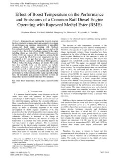
Transcription of Solar Powered Vehicle - International Association of Engineers
1 Abstract The renewable energy is vital for today s world as in near future the non renewable sources that we are using are going to get exhausted. The Solar Vehicle is a step in saving these non renewable sources of energy. The basic principle of Solar car is to use energy that is stored in a battery during and after charging it from a Solar panel. The charged batteries are used to drive the motor which serves here as an engine and moves the Vehicle in reverse or forward direction. The electrical tapping rheostat is provided so as to control the motor speed. This avoids excess flow of current when the Vehicle is supposed to be stopped suddenly as it is in normal cars with regards to fuel. This idea, in future, may help protect our fuels from getting extinguished. All recent electric vehicles present drive on AC power supplied motor.
2 The setup requires an inverter set connected to battery through which DC power is converted to AC power. During this conversion many losses take place and hence the net output is very less and lasts for shorter duration of time. Although this is cheaper the setup and maintenance required is much more in AC drive than DC drive. The Vehicle designed is controlled by ELECTRICAL means and not by ELECTRONIC means Index Terms Motor, Rheostat Control, Lead-acid batteries, Solar panel, Battery Cycle. I. INTRODUCTION T Energy is one of the most vital needs for human survival on earth. We are dependent on one form of energy or the other for fulfilling our needs. One such form of energy is the energy from FOSSIL FUELS. We use energy from these sources for generating electricity, running automobiles etc.
3 But the main disadvantages of these FOSSIL FUELS are that they are not environmental friendly and they are exhaustible. To deal with these problems of FOSSIL FUELS, we need to look at the NON-CONVENTIONAL SOURCES of energy. With regard to this idea we have designed an Electrical Vehicle that runs on Solar energy. The Vehicle designed is a Manuscript received June 17,2010. This work was supported in part by the SRM University. This work was a part of the final year engineering project of Yogesh wamborikar, Arjun Sharma and Ujjwal Kumar F. A. Yogesh Wamborikar was with the SRM university as a student of Electrical and ElectronicsEngineering,Chennai,TamilNadu ,India S. B. Author, Abhay Sinha., is with SRM University, Chennai. He is a final year student of Electrical and Electronics Department in SRM three wheel drive and can be used for shuttle and short distances.
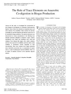
4 As these vehicles form the future of the automotive industry, we need to concentrate on improving their design and making them cost effective. This Vehicle is an initiative in this direction. II. BASIC FUNCTIONAL DIAGRAM Fig. 1 Basic block Diagram Representation of Solar Vehicle The above diagram gives an overview of the working of Solar Vehicle . Sun is the main source of energy for the Vehicle . Energy from Sun is captured by the Solar panels and is converted to electrical energy. The electrical energy thus formed is being fed to the batteries that get charged and is used to run 24 V DC high torques DC series motor. The shaft of the motor is connected to the rear wheel of the Vehicle through chain sprocket. The batteries are initially fully charged and thereafter they are charged by panels.
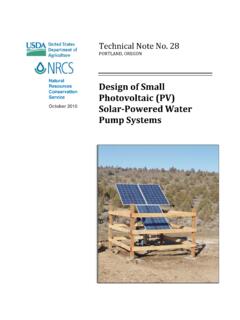
5 This helps in completing the charging-discharging cycle of the batteries, which is very important for proper working of batteries. III. BASIC CIRCUIT DIAGRAM The fig 2 shown below represents the connections of the motor for forward and backward motion. The connections are made from battery to motor via switch, controller unit and the Solar panel. As stated before, the motor used in this Vehicle is 24 V dc series motor. There are four terminals on motor, namely A1, A2, F1, F2, as A1, A2 are the armature terminals and they are internally shorted. All the connections are made keeping the DPDT switch at the centre. The either connections on DPDT switch are made for forward direction motion of motor and the next side of DPDT switch is made for reverse direction of motor. The motor will work as the switch is kept in either of the directions as per requirements.
6 The A2 is directly taken from battery to the positive side of DPDT switch and F2 is taken via controller unit to the negative terminal of switch. For the DPDT the centre Solar Powered Vehicle Yogesh Sunil Wamborikar, Abhay Sinha Proceedings of the World Congress on Engineering and Computer Science 2010 Vol II WCECS 2010, October 20-22, 2010, San Francisco, USAISBN: 978-988-18210-0-3 ISSN: 2078-0958 (Print); ISSN: 2078-0966 (Online)WCECS 2010 terminals are given the upper side as positive from battery and the lower as the negative from battery. The controller unit used here is a high resistance setup box which can withstand up to the current of 60amps. Now the A1, A2 are the internally shorted terminals of the motor. Thus either of the one is the main and another one is the dummy.
7 In case of our motor the A1 terminal is dummy and A2 is the main terminal. Thus all connections are made keeping A2 as the main terminal. In the switch the A2 and F1 are the terminals that are responsible for the reverse motion of motor. All the connections are directly to switch, A2 is given to positive and F1 given to the negative of switch. Fig. 2 Circuit diagram for the movement of the Vehicle IV. COMPONENTS USED Various types of electrical components were used for making the Solar Powered Vehicle . A list of these components used with their range and the specific quantities that were required for making the Solar Vehicle is given in the following table. TABLE I LIST OF VARIOUS COMPONENTS USED Components used Range Quantity Batteries( heavy inverter batteries) 24V 190Ah 2*12V Solar module 140Wp(Watt Peak) 1 Connecting Cables Motor high voltage cables.
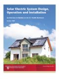
8 Solar module to charge controller Charge controller to battery 10 meters 1 meter 1 meter Motor High torque DC motor 1Hp=746W 1 Apart from the above listed components the main component that is responsible for speed control of the motor is the speed control switch. It is defined as follows:- A. SPEED CONTROL SWITCH The speed control of the DC motor is the essential part of the Vehicle . For controlling speed of the motor, a switch was designed with 8 tapping, giving different values of resistance at each tapping, hence limiting the current that flows in the motor. The switch uses pure Nichrome wire for resistances. It uses a 8 tapping DC switch. The front view of the switch is as follows:- Fig. 3. The front view of the speed control unit The switch has been provided with two terminals; one for the motor connections and the other for the battery connections.
9 The arrangement of the switch is more or less like a rheostat. The different tapping act as resistance points. With each increase in the tapping value the value of resistance decrease, thus at the last tapping the motor will run at the highest speed as the limiting resistance will be minimum whereas the high torque condition of the motor will arise when the minimum tapping will be used, since the limiting resistance will be maximum. The picture showing the view of the tapings is shown below in fig 4. It can be easily concluded that two coils are connected in a series to give one taping hence increasing the resistance. Fig 4. The upper view if Speed control switch depicting the taping connections Proceedings of the World Congress on Engineering and Computer Science 2010 Vol II WCECS 2010, October 20-22, 2010, San Francisco, USAISBN: 978-988-18210-0-3 ISSN: 2078-0958 (Print); ISSN: 2078-0966 (Online)WCECS 2010 The value of resistance at each taping is given in the table below.
10 This resistance value is used for controlling the 1 hp motor. TABLE II VALUES OF RESISTANCE AT VARIOUS TAPINGS OF THE SWITCH B. Solar PANEL DETAILS - 140Wp The Solar panel used in the Solar Vehicle is of the rating of 140 WP. The main point that should be kept in mind while making a Solar Vehicle is the mounting of the Solar panel. The panel should be mounted in such a way that it receives maximum sun rays so that it gives its maximum efficiency. For the Vehicle designed, we have mounted the Solar panel in SOUTH-EAST direction during the time 6 AM to AM. After that the panel is changed to a SOUTH-WEST direction. We have used the conventional roof-top mounting technique for the Solar panel A 6 feet by 4 feet plywood has been used and mounted on the top of Vehicle . The Solar cell used in the Vehicle is multi-crystalline.