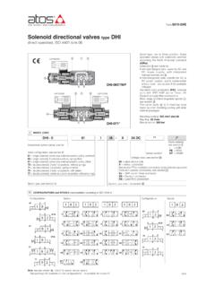
Transcription of Solenoid directional valves type DHE - Atos
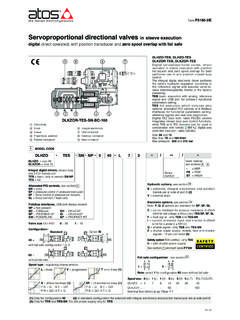
1 1421210 directional valves typeDHEdirect operated , high performances, ISO 4401 size 06 Table E015-5/E1 MODEL CODEE0157163617567/A63/A61/A672 CONFIGURATIONS and SPOOLS (representation according to ISO 1219-1)Spool type, two or three position directoperated valves with high performancethreaded solenoids certified accordingthe North American standard are made by: wet type screwed tube, different for ACand DC power supply, with integratedmanual override pin interchangeable coils, specific for ACor DC power supply, easily replaceablewithout tools - see section foravailable voltagesStandard coils protection IP65optionalcoils with IP67 AMP Junior Timer or leadwire connections. Wide range of interchangeable spools ,see section .The valve body is 3 chamber typemade by shell-moulding casting with wideinternal surface: ISO 4401 size 06 Max flow:80 l/minMax pressure:350 bar08491901620917391584195936397941/9 ..BADHE-061*/WP-AC0 20 201210/21/22/2(2)01 0 201 0 201 0 201 0 201 0 2 ConfigurationsSpoolsConfigurationsSpools BADHE-071*-DC.
2 directional control valves size 06 Valve configuration, see section 61 = single Solenoid , center plus external position, spring centered63 = single Solenoid , 2 external positions, spring offset67 = single Solenoid , center plus external position, spring offset71 = double Solenoid , 3 positions, spring centered75 = double Solenoid , 2 external positions, with detentSpool type, see section .Series numberOptions, see note 1 at section .Voltage code, see section 00-AC =AC solenoids without coils00-DC = DC solenoids without coilsX = without connectorSee section for available connectors, to be ordered separatelyCoils with special connectors, see sectionXJ= AMP Junior Timer connectorXK= Deutsch connectorXS= Lead Wire connection11-DHE - 0611/AX24 DC**/*Seals material, see section :-=NBR PE= FKMBT = HNBR6/7(1)Note: see also section , note 3, for special shaped spools(1): spool type 6/7 available only for configuration 61, not available for version /A (2): not available for configuration 75 4 NOTES1 Options A = Solenoid mounted at side of port B (only for single Solenoid valves ).
3 In standard versions, Solenoid is mounted at side of port A. WP = prolonged manual override protected by rubber cap. The manual override operation can be possible only if the pressure at T port is lower than 50 bar - see section . WPD/HE-DC = (only for DHE-DC) manual override with detent, to be ordered separately, see tab. K150 L1, L2, L3 = (only for DHE-DC) device for switching time control, installed in the valve Solenoid , see section .For spools 4 and 4/8 only device L3 is available. FI, FV = with proximity or inductive position switch for monitoring spool position: see tab. E110. MV, MO = auxiliary hand lever positioned vertically (MV) or horizontally (MO). For available configuration and dimensions see table Type of electric/electronic connector DIN 43650, to be ordered separately 666 = standard connector IP-65, suitable for direct connection to electric supply source. 667 = as 666, but with built-in signal led.
4 669 = with built-in rectifier bridge for supplying DC coils by alternate current (AC 110V and 230V - Imax 1A). E-SD = electronic connector which eliminates electric disturbances when Solenoid valves are Spools - spools type 0and 3are also available as 0/1and 3/1with restricted oil passages in central position, from user ports to tank. - spools type 1, 4, 5 and 58are also available as 1/1, 4/8,5/1 and 58 are properly shaped to reduce water-hammer shocks during the swiching. - spools type 1, 1/2, 3, 8are available as 1P, 1/2P, 3P, 8 Pto limit valve internal leakages. - Other types of spools can be supplied on (1) Coil can be supplied also with 60 Hz of voltage frequency: in this case the performances are reduced by 10 15% and the power consumption is 52 VA.(2) Average values based on tests preformed at nominal hydraulic condition and ambient/coil temperature of 20 C.(3) When Solenoid is energized, the inrush current is approx 3 times the holding DC14 DC24 DC28 DC48 DC110 DC125 DC220 DC110/50 AC230/50 AC115/60 AC230/60 AC110/50 AC - 120/60 AC230/50 AC - 230/60 AC666or66766930 W58 VA(3)80 VA(3)30 W5 ELECTRIC FEATURESE xternal supplynominal voltage 10%Type of connectorPowerconsumption(2)Code of spare coilDHEV oltage code12 DC14 DC24 DC28 DC48 DC110 DC125 DC220 DC110/50/60 AC230/50/60 AC115/60 AC230/60 AC110 RC230 RCCOE-12DC COE-14 DCCOE-24DC COE-28DC COE-48DC COE-110DC COE-125DC COE-220DC COE-110/50/60AC (1)COE-230/50/60AC (1)COE-115/60 ACCOE-230 Coils characteristics Insulation class H(180 C) for DC coils F(155 C)
5 For AC coils Due to the occuring surface temperatures of the Solenoid coils, the European standards EN ISO 13732-1and EN ISO 4413 must be taken into account Protection degree to DIN EN 60529 IP 65(with connectors 666, 667, 669 correctly assembled) Relative duty factor 100% Supply voltage and frequency See electric feature Supply voltage tolerance 10% Certification CURUSN orth American StandardPorts P,A,B: 350bar; Port T 210bar for DC version; 160bar for AC version Mineral oils Hydraulic fluidNBR, FKM, HNBRFKMNBR, HNBRDIN 51524 ISO 12922HL, HLP, HLPD, HVLP, HVLPDHFDU, HFDRHFCS uitable seals typeClassificationRef. Standard Flame resistant without water Flame resistant with water3 MAIN CHARACTERISTICS,SEALS AND HYDRAULIC FLUID - for other fluids not included in below table, consult our technical office NBR seals (standard) = -20 C +60 C, with HFC hydraulic fluids = -20 C +50 C Seals, recommended fluid temperature FKM seals (/PE option) = -20 C +80 C HNBR seals (/BT option) = -40 C +60 C, with HFC hydraulic fluids = -40 C +50 C Recommended viscosity 15 100 mm2/s - max allowed range 500 mm2/s Fluid contamination class ISO 4406 class 21/19/16 NAS 1638 class 10, in line filters of 25 mm (b25 _>75 recommended)
6 Operating pressure Assembly position / location Any position Subplate surface finishing Roughness index Ra 0,4 - flatness ratio 0,01/100 (ISO 1101) MTTFd values according to EN ISO 13849 150 years, for further details see technical table P007 Flow direction As shown in the symbols of table Rated flow See diagrams Q/Dp at section Maximum flow 80 l/min, see operating limits at section Standard execution = -30 C +70 C Ambient temperature /PE option = -20 C +70 C /BT option = -40 C +70 CE0156Q/DP DIAGRAMS based on mineral oil ISO VG 46 at 50 C7 OPERATING LIMITS based on mineral oil ISO VG 46 at 50 CThe diagrams have been obtained with warm solenoids and power supply at lowest value (Vnom- 10%).
7 The curves refer to application with symmetricalflow through the valve ( P A and B T). In case of asymmetric flow and if the valves have the devices for controlling the switching times the operatinglimits must be TIMES (average values in msec) DHE 10 - 25 20 - 40 30 - 50 15 - 25 DHE-*/L1 60 60 DHE-*/L2 80 80 DHE-*/L3 150 150 Valve Switch-on Switch-off Switch-onSwitch-off AC AC DCDCTest conditions:- 36 l/min; 150 bar- nominal voltage- 2 bar of counter pressure on port T- mineral oil: ISO VG 46 at 50 CThe elasticity of the hydraulic circuit and the variations of the hydrauliccharacteristics and temperature affect the response devices are used to control the valve s switching time(only for DC version)
8 And therefore reduce the hammeringshocks in the hydraulic L1, L2, L3 control the switching time in both movingdirections of the valve spool by means of calibrated restrictorsinstalled in the Solenoid directionSpool type P A P B A T B T P T DHEV alve pressure drop Dp [bar]Flow rate [l/min]GFEDCBAFlow rate [l/min]Inlet pressure [bar]Flow rate [l/min]Inlet pressure [bar]DHE- ACDHE- DCADABCBCDE 0, 0/1 A A C C D 1, 1/1, 1/9 D C C C 3, 3/1 D D A A 4, 4/8, 5, 5/1, 49, 58, 58/1, 94 F F G C E 1/2, 0/2 D D D D 6, 7, 16, 17 D D D D 8 A A E E 2 D D 2/2 F F 09, 19, 90.
9 91 E E D D 39, 93 F F G G A 1, 1/2, 8 0, 0/1, 1, 1/2, 3, 8 B 0, 0/1, 0/2, 1/1, 1/9, 3 0/2, 1/1, 6, 7, 1/9, 19 C 3, 3/1, 6, 7 D 2, 2/2 E 2, 2/2 - Curve Spool type AC DC4, 4/8, 5, 5/1, 16, 17,19, 39, 58, 58/1, 09,90, 91, 93, 943/1, 4, 4/8, 5, 5/1, 16,17, 19, 39, 49, 58, 58/1,09, 90, 91, 93, 94 Note: for the electric characteristics refer to standard coils features - see section 9 DEVICES FOR THE SWITCHING TIME CONTROLO ptions -XJCoil type COEJAMP Junior Timer connectorProtection degree IP67 Options -XKCoil type COEKD eutsch connectorDT-04-2P maleProtection degree IP67 Options -XSCoil type COESLead Wire connectionCable lenght = 180 mmDeutsch connector DT-04-2 PLead Wire connectionAMP Junior timer connector11 COIL WITH SPECIAL CONNECTORS only for voltage supply 12, 14, 24, 28 VDCL1= 1,1 mmL2= 0,9 mmL3= 0,7 mm Valve AC DC (cycles/h) (cycles/h)10 SWITCHING FREQUENCY DHE + 666 / 667 7200 15000 L* DIMENSIONS [mm]ISO 4401: 2005 Mounting surface: 4401-03-02-0-05 Fastening bolts: 4 socket head screws:M5x30 class Tightening torque = 8 NmSeals.
10 4 OR 108 Ports P,A,B,T: = mm (max)P = PRESSURE PORTA, B= USE PORTT = TANK PORTDHE-06(DC)DHE-07(DC)The use of plug-in restrictors in valve s ports P or A or B may be necessary is case of particular conditionsas long flexible hoses or the presence of accumulators which could cause at the valve switching instanta-neous high flow peaks over the max valve s operating : 1,5 kgMass: 2 kgDHE-06(AC)DHE-07(AC)Mass: 1,4 kgMass: 1,8 kgOption /WPOption /WP09/1615 MOUNTING SUBPLATESM odelPorts locationGAS PortsA-B-P-T Counterbore[mm]A-B-P-TMass[kg]BA-202BA-2 04BA-302 Ports A, B, P, T underneath;Ports P, T underneath; ports A, B on lateral sidePorts A, B, P, T underneath3/8"3/8"1/2" 25,5301,21,81,8 The subplates are supplied with 4 fastening bolts M5x50. Also available are multi-station subplates and modular subplates. For further details see table from X14 ELECTRIC CONNECTORS ACCORDING TO DIN 43650 (to be ordered separately)666, 667(for AC or DC supply)669(for AC supply)666, 667 1= Positive 2= Negative = Coil ground669 1,2 = Supply voltage VAC 3 = Coil groundCONNECTOR WIRINGSUPPLY VOLTAGES666 Allvoltages66724 AC or DC110 AC or DC220 AC or DC669110/50 AC110/60 AC230/50 AC230/60 AC Standard manual override PIN Note: for electronic connectors type E-SD, see tab.