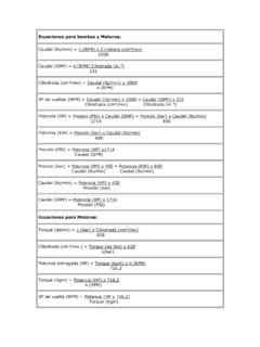
Transcription of Solenoid directional valves type DKI, DKU, DKOR - ADIGRA
1 Atos spa21018 Sesto Calende, Italy - Fax 0331 920005 Solenoid directional valves typeDKI, DKU, DKOR direct operated, ISO/ cetop size 05 Table E020-10/EDKI,DKU and DKOR are spool type,three or four way, two or three positiondirect operated Solenoid valves desi-gned to operate in oil are operated by wet and pressuresealed Solenoid with manual overri-de: AI Solenoid suitable for AC and DCsupply; AU Solenoid for DC supply withimproved performance; AOR Solenoid for DC supply withhigh parts are protected, lubricatedand cushioned in casting are 5 cham-bers machined by transfer lines andthen cleaned by thermal flow paths largely cored withextrawide channels to tank for lowpressure spools available ina wide variety of and DKOR valves can be sup-plied with optional devices for controlof switching electric/electronic connectors able to satisfy the requirements ofmodern machines for electric interfa-ces are fully encapsulated (class H).
2 In DKI and DKU coils are easily repla-ceable without the aid of execution suitable for mounting ISO/ cetop flow up to 100 l/min for DKI/DKUand up to 120 l/min for pressure: 315 1 directional control valves ISO/ cetop 05 DKI-1= Solenoid AI for AC and DC supplyDKU-1= Solenoid AU for DC supplyDKOR-1= Solenoid OO for DC supplyValve configuration, see table 61 = single Solenoid , center plus external position,spring centered63 = single Solenoid , 2 external positions, spring offset67 = single Solenoid , center plus external position,spring offset70 = double Solenoid , 2 external positions, withoutspring71 = double Solenoid , 3 positions, spring centered75 = double Solenoid , 2 external positions, with detent(not available for DKOR models)Other configurations are available on type, see table.
3 Design numberSynthetic fluidsWG =water glycolPE= phosphate ester/A**63/*1 MODEL CODEE0201/2 Options, see note 1 at section .X24 DCExternal supply voltage see section 00= valve without coils (only for DKI andDKU).-X = without connectorSee note 2 at section for available connectors,to be ordered separatelyPURGE SCREWPURGE SCREWDKIDKUDKORW here the symbol doesn't show the hydraulic connection (*), itdepends on the central configuration of the spool - see table .2 CONFIGURATION3 SPOOLS - for intermediate passages, see tab. note 3 at section .00/279411/284922/2901630917491585195/19 3639-171*-1630/2/A-1631/2/A-1700/2-1701/ 2-161*/A-1750/2-1751/2-167*/A-1630/2-163 1/2-161*-167*only for DKI/DKUconnectorconnectorAssembly position / locationCommissioningSubplate surface finishingRoughness index flatness ratio 0,01/100 (ISO 1101).
4 Ambient temperaturefrom -20 C to +70 oil as per DIN 51524 .. 535; for other fluids see section .Recommended viscosity15 100 mm2/s at 40 C (ISO VG 15 100).Fluid contamination classISO 19/16, achieved with in line filters at 25 m value to 25 75 (recommended).Fluid temperatureT 80 C if T 60 C select /PE sealsFlow directionAs shown in the symbols of tables and .Operating pressureRated flowSee diagrams Q/ p at section .Maximum flow100 l/min for DKI and DKU; 120 l/min for DKOR, see operating limits at section .Relative duty factor100%Supply voltage and frequencySee model code at section .Supply voltage tolerance 10%For correct AC operation, the valve must be full of hydraulic fluid, otherwise some vibrations mayoccur.
5 In this case fill the valve with oil by opening the screw , see sketch at section and .A check valve on T line aids to keep valve CHARACTERISTICS OF DKI, DKU AND DKOR directional VALVES5 NOTES1 OptionsA= Solenoid mounted at side of port B (only for single Solenoid valves ). In standard versions, Solenoid is mounted at side of port = prolonged manual override protected by rubber cap (standard for DKOR models).L, L1, L2, L3, LR, see section = device for controlling switching time (only for DKU and DKOR models). Not available for valves with connectorsE-SA or E-SE. For spools 4, 4/8, 5/1 only device L1 is * = with proximity switch for monitoring spool position: see tab. Type of electric/electronic connector with connector DIN 43650 to be ordered separatelySP-666= standard connector IP-65 for direct connection to electric supply as SP-666, but with built-in signal = with built-in rectifier bridge for supplying DC coils by alternate current (AC).
6 E-SA= electronic connector (only for DKI and DKU valves ) which improves performances and give faster shifting times for DC Solenoid suppliedby AC electronic connector (only for DKI and DKU valves ) which improves performances and reduces power consumption for DC Solenoid sup-plied by DC electronic connector which permits switching of Solenoid valves by a low power signal (max 20mA).E-SD= electronic connector which eliminates electric disturbances when Solenoid valves are : disturbance suppressor devices, similar to E-SD are, standard, built in all E-SA, E-SE, Spools- spools type 0/2, 1/2, 2/2 are only used for two position valves : single Solenoid valves , type DK*-163*/2; double Solenoid valves type DK*-170*/2and DK*-175* spools type 0 and 3 are also available as 0/1 and 3/1 that, when in centre position, oil passage from ports to tank are spools type 1,4 and 5 are also available as 1/1, 4/8 and 5/1.
7 They are properly shaped to reduce water-hammer shocks during the that the configuration of spool 5/1 is inverted in respect with spool 5: see section .- spools type 1,3 and 1/2 are also available as 1P, 3P and 1/2P to limit valve Other types of spools can be supplied on request.(1) Tolerance on the nominal voltage is 10%.(2) Other supply voltages are available onrequest: 28DC, 110DC, 125DC, 220DC,48/50/60 AC.(3) Coil can be supplied also with 60 Hz of volta-ge frequency: in this case the performancesare reduced by 10 15% and the powerconsumption is 55 VA.(4) Average values based on tests performed atnominal hydraulic condition and ambient/coiltemperature of 20 C.(5) In a cycle, where Solenoid is energized/dee-nergized in 1 second (1 Hz), the averagepower consumption is 13 W; for longer cycles,the power consumption is Solenoid is energized the inrush currentis 9 A at 12 VDCand 6 A at 24 VDCcorrespon-ding to power consumption peak of 130 current peaks persist for a periodshorter than 100 msec and they must beconsidered when electric circuit is designed.
8 (6) When Solenoid is energized the inrush cur-rent is 7 A at 110 VACand 3,5 A at 230 VAC;the power consumption peak is 800 VA;these current peaks persist for a period shor-ter than 40 msec and they must be conside-red when electric circuit is designed.(7) When Solenoid is energized, the inrush cur-rent is approx 3 times the holding current values correspond to a powerconsumption of about 350 VA.(8) Protection class H; Duty cycle: 100%.Connector protection degree: IP FEATURESE xternal supplyType ofPowerCode of spare coilColourValvenominal voltageconnector consumption(8)of coil(1) (2)(4)labelDKIandDKUDKIDKORDIRECTCURRENT 6 DC12 DC24 DC48 DCSP-666orSP-66752 WSP-CAU-6DC/ 80SP-CAU-12DC /80SP-CAU-24DC /80SP-CAU-48DC /80browngreenredsilverbrowngreenredsilve rgoldblueyellowwhitelight bluesilver12 DC24 DC110/50 AC120/60 AC230/50 AC230/60 AC110/50 AC120/60 AC230/50 AC230/60 ACE-SEE-SASP-669SP-666orSP-667SP-666orSP -667SP-66913 W (5)105 VA (6)95 VA (6)105 VA (6)95 VA (6)58 VA53 VA58 VA53 VA110 VA (7)
9 40 W46 W46 VA42 VA46 VA42 VA SP-CAU-6DC /80SP-CAU-12DC /80SP-CAU-24DC /80SP-CAU-48DC /80SP-CAU-110RC /80SP-CAU-230RC /80SP-CAI-110/50/60AC /80SP-CAI-120/60AC /80SP-CAI-230/50/60 AC /80SP-CAI-230/60AC /80 ALTERNATECURRENTALTERNATECURRENTDIRECTCU RRENTALTERNATECURRENT110/50 AC (3)120/60 AC230/50 AC (3)230/60 AC12 DC24 DC110 DC220 DC110/50 AC120/60 AC230/50 AC230/60 ACAny position for all valves except for type - 170* (without springs) that must be installed with horizontalaxis if operated by impulsesPorts P,A,B: 315 bar;Port T with port Y plugged: 120 bar for DKI; 160 bar for DKU and 210 bar for DKOR;On port T pressure up to 315 bar are allowed if port Y is drained;For versions with proximity switches (/FI/NC and /FI/NO versions)
10 Port Y must be drained04,E0207Q/ P DIAGRAMSB ased on fluid viscosity of 43 mm2/s at 40 =Spools 0, 0/2, 1, 1/2, 3, 6, 7, 8, with E-SA or = Spools 0, 1, 1/2, 3 with electric = Spools 2, 2/2, *9, 9* with E-SA or E-SE = Spools 0/2, 4, 5, 6, 7 with electric = Spools 2, 2/2, *9, 9* with electric = Spools 0, 0/2, 1, 1/2, 3, 6, 7, 8 with E-SA or = Spools 0, 1, 1/2, 8 with electric = Spools 0/2, 3, 6, 7 with electric = Spools 2, 2/2, *9, 9* with E-SA or E-SE = Spools 2, 2/2, *9, 9* with electric = Spools 4, 5 with electric = Spools 0, 0/2, 1, 1/2, = Spools 3, 6, = Spools 2, 2/2, *9, 9*T = Spools 4, FOR SWITCHING TIME CONTROLT hese devices are only available for DKU and DKOR without E-SA or E-SE and cancheck the switching time and therefore reduce the coil hammering in the circuit.