Transcription of Solenoid Operated Directional Valves DG4V-3S, X4 …
1 Vickers Solenoid Operated Directional Valves Explosion Proof ATEX, UL, CSADG4V-3S, X4 & X5 DG4V4-01, X52 eaton Vickers D03/NG6 and D05/NG10 Solenoid Operated Directional Valves Explosion Proof V-VLDI-MC015-E January 2011 Table of ContentsIntroduction General Description ..3 Features and Benefits ..3 Characteristics ..3 Typical Side View ..3 Model ..4 Spool Data ..5 Functional Symbol ..5 Operating Data ..6 Performance Data ..7 Installation Dimensions ..9 Application Data ..103 eaton Vickers D03/NG6 and D05/NG10 Solenoid Operated Directional Valves Explosion Proof V-VLDI-MC015-E January 2011 IntroductionGeneral DescriptionThese Solenoid Operated Directional control Valves are for directing and stopping flow at any point in a hydraulic system.
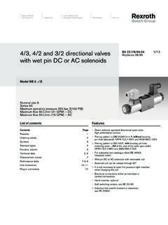
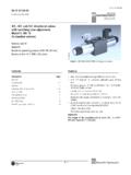
2 This series has been specially designed and devel-oped for equipment that has been installed in new applica-tions in potentially explosive , X4 option ATEX approval Hazardous locations - Ex II 2 G; Zone 1 and Zone 2. Protection type - EEx me II T4; increased safety and encapsulated dg4v -3S and DG4V4, X5 option ATEX, UL, and CSA approv- al; complies to all 3 direc- tives ATEX approval; hazardous locations - Ex II 2 G; Zone 1 and Zone 2; protection type EEx d IIB T*, flameproof UL and CSA approval; hazardous locations - Class 1, Group C/D; Class 2, Group E/F/G.
3 Division 1 & 2 CharacteristicsDG4V-3S-X4 & X5-6* Design Mounting interfaceISO 4401 size 03 size D03 CETOP RP65H, size 3 DIN 24340, NG6 Basic characteristicsMaximum pressure: 350 bar (5075 psi) Maximum flow: Up to 40 l/min ( USgpm) DG4V4-01, X5-10 Design Mounting interface ISO 4401 size 05 size D05 CETOP RP65H, size 5 DIN 24340, NG10 Basic characteristicsMaximum pressure 315 bar (4500 psi) Maximum flow up to 80 L/min (21 USgpm)Features and BenefitsNew expanded product offering for hazardous envi-ronments, opening up new opportunities. Multi-fluid capability without need to change seals. Higher sustained machine productivity and higher up| time because of proven fatigue life and endurance, tested over 10 million limitsMinimum ambient: -20 C (-4 F) Maximum ambient: +70 C (158 F) Fluid temperature For mineral oil Minimum = -20 C (-4 F) Maximum = +70 C (158 F) The temperature limits of these Valves are subject to specific operating condi-tions.
4 Please refer to the Instruction for Use document supplied with each eaton Vickers D03/NG6 and D05/NG10 Solenoid Operated Directional Valves Explosion Proof V-VLDI-MC015-E January 2011 Model Code Directional Control Valve dg4v -3S-D03/NG6 DG4V4-01-D05/NG10 Subplate Mounted, Solenoid Operated , ISO 4401size Spool type 0, 2, 6, 8* * Other spools are available on request Spool/Spring ArrangementA Spring offset, end to end AL As A but left hand build B Spring offset, end to center BL As B but left hand build C Spring centered Manual Override Options Blank Plain overrides in sole-noid end only Solenoid Energisation IdentityBlank ANSI B93 9 (Sol.)
5 A flow from P to A )V Solenoid a at port A end of valve and/or Solenoid b at B end of valveNote: 8 type spool must be ordered with V in model code Coil TypeX4 (only available on dg4v -3S) ATEX approval; Increased safety and encapsulated solenoids to IEC classifica- tion EEx me II T4X5 ATEX, ExdIIC2G, approval; Zone 1 and 2, protection type flame proof. UL and CSA approval; Class 1, group C/D, Class 2 group, group E/F/G/; Division 1 & 2 Coil rating X5 Coil AvailabilityA 110V AC, 50 HZER 120V AC, 60 HZC 220V AC, 50 HZES 240V AC, 60HZ (only for DG4V4-01)H 24V DCOJ 48V DCP 110V DCX4 Coil AvailabilityH 24V DCG 12V DC Tank Port Rating4 70 bar, for X5 Valves only7 210 bar, for X4 Valves only Design Number60 dg4v -3S61 8C spool only, dg4v -3S10 DG4V4-01 Port orifice plugs Blank No orificeP** P port ** orifice size in 1/10 mm (03 = )A** A port ** orifice size in 1/10 mm (03 = )B** B port ** orifice size in 1/10 mm (03 = )T** T port ** orifice size in 1/10 mm (03 = )
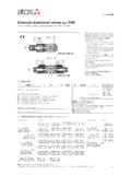
6 dg4v -* * * * * M ** ** * ** (P*-A*-B*-T*)1233445566778899101015 eaton Vickers D03/NG6 and D05/NG10 Solenoid Operated Directional Valves Explosion Proof V-VLDI-MC015-E January 2011 Functional Symbols Spools5 EATONV ickersSolenoid Operated DirectionalValves Catalog V-VLDI-MC008-E September 2008 FunctionalSymbols,SpoolsSolenoids identified (specify A in model code)Functional symbols relatedto Solenoid identity A and/or B according toNFPA/ANSI standards, Solenoid A gives flow P to A, Solenoid B gives flow P to B(as applicable).Available spool options(illustrated to the right)Configurations include3-position and 2-position,spring centered, spring off-set and no-spring identified toEuropean standards(specify V in model code)Functional symbols relatedto Solenoid identity A and/or B according toEuropean convention A adjacent to A port, Solenoid B adjacentto B port of.
7 LoSPTABSol. BPTABSol..loST r ansient r ansient condition only3 The valve function schematics apply to both European Solenoid Valves ,two position, detentedSingle Solenoid Valves , Solenoid at port A endDouble Solenoid Valves , springcenteredSingle Solenoid Valves , Solenoid at port B endDouble Solenoid Valves ,two position, detentedSingle Solenoid Valves , Solenoid at port A endDG4V-3-8C(V) dg4v -3-8BL(V) dg4v -3-8B(V) dg4v -3-*C(V) dg4v -3-*B/F(V) dg4v -3-*BL/FL( V) dg4v -3-*N(V) dg4v -3-*A(V) dg4v -3-*AL(V)D ouble Solenoid Valves ,spring centeredSingle Solenoid Valves , Solenoid at port B endFor Use withSolenoid Spool Type SolenoidB Allexcept 8 AA 8 only BLocation of Solenoid "A" or "B" shownrelative to the hydraulic work port.
8 "A" and "B" designations are printedon the name label adjacent tothe Solenoid indicator lights,illustrated of Solenoid "A" or B" shownrelative the hydraulic work Use withSolenoid Spool Type SolenoidB Allspools A"A" and "B" designations are printedon the name label adjacent tothe Solenoid indicator lights,illustrated eaton Vickers D03/NG6 and D05/NG10 Solenoid Operated Directional Valves Explosion Proof V-VLDI-MC015-E January 2011 Operating Data Data is typical, with fluid at 36 cST (168 SUS) and 50 C (122 F) Valve size dg4v -3S DG4V4-01 Pressure limits: P, A and B ports 350 bar 315 bar T port 70 bar for X5, 210 bar for X4 70 barFlow rating See performance data See performance data Relative duty factor Continuous rating (ED = 100%) Continuous rating (ED = 100%) Type of protection IEC 144 class IP66 IEC 144 class IP66 Permissible Voltage Fluctuation DC 10% DC 10% Typical response times at 100% rated volts measured from DC AC application/removal of voltage to full spool displacement of 2C spool at.
9 Flow Rate at P-A, B-T 20 l/min 20 l/min 40l/min 40l/min Pressure, P Port 175 bar 175 ms 175 ms 175 ms Energizing 60 ms 100 ms 60 ms 100 ms De-energizing 40 ms 100 ms 40 ms 100 msPower consumption, solenoids at rated voltage and 20 C (68 F) X4 coils 12V DC Solenoid rating - type G 30W 30W 24V DC Solenoid rating - type H 30W 30W X5 coils 24V DC Solenoid rating - type H 17W 17W 48V DC Solenoid rating - type OJ 17W 17W 110V DC Solenoid rating - type P 17W 17W 110V AC, 50Hz, Solenoid rating - type A 20W 20W 120V AC, 60Hz, Solenoid rating - type ER 20W 20W 220V AC, 50Hz, Solenoid rating - type C 20W 20W 240V AC, 60Hz, Solenoid rating - type ES 20W 20W7 eaton Vickers D03/NG6 and D05/NG10 Solenoid Operated Directional Valves Explosion Proof V-VLDI-MC015-E January 2011 Performance DataDG4V-3S.
10 X4 and X5 Maximum flow ratesTypical with mineral oil at 36 cSt ( SUS) and a specific gravity of Performance based on full power Solenoid coils warm and operating at 90% rated , X5 Maximum flow ratesTypical with mineral oil at 36 cSt ( SUS) and a specific gravity of Performance based on full power Solenoid coils warm and operating at 90% rated Code dg4v -3S0A(L) 20B(L) & 0C, 0F 12A(L) 22B(L) & 2C 26B(L) & 6C, 6F 38B(L) & 8C 4 Spool/Spring DG4V4-01 Code AC DC0A(L) 1 4OB(L) & OC, OF 1 42A(L) 1 42B(L) & 2C 1 46B(L) & 6C, 6F 2 48B(L) & 8C 3 4 Flow ratePressure Drop5000 PSIBar4000300020001000350280210140700 00432104812162024204060801001202832 USgpmL/min0 2030l/min248 USgpmFlow ratepsibar500040003000200010000050100150 200250300350 Pressure Drop1234100 610408 eaton Vickers D03/NG6 and D05/NG10 Solenoid Operated Directional Valves Explosion Proof V-VLDI-MC015-E January 2011 Performance DataFlow Curves dg4v -3S, X4 & X5 Spool/Spring Spool P to A P to B A to T B to T P to T B to A Code Positions0A(L)C Both 5 5 2 2 -0B(L)C & 0C De-energized - - - - 4 - Energized 4 4 2 2 - -2A(L) Both 6 6 5 5 - -2B(L) & 2C Energized 5 5 2 2 - -6B(L)