Transcription of SOLID STATE 4-PIN SOIL RESISTANCE METER
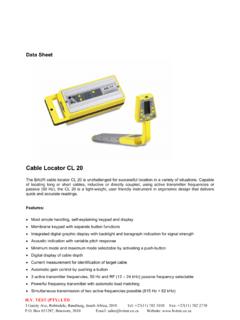
1 SOLID STATE4-PIN soil RESISTANCE METER @SINCE 1919 NILSSON ELECTRICAL LABORATORY, IN ELECTRONIC AND ELECTRICAL MEASUREMENTS333 WEST SIDE AVENUE, JERSEY CITY, 07305 TEL. (201 )-521 -4860 FAX. (201 )-521 -4863 NILSSON MODEL 400 4-PIN soil RESISTANCE METERCONTENTSPAGEDESCRIPTION .. 3~.OPERATING INSTRUCTIONS4 Pin Method .. 4 soil Box .. 53 Pin Method .. 52 Pin Method .. 6 Single Probe Method .. 6 OPERATING NOTES .. 7 MAINTENANCE .. 7**RECHARGEABLE12 VOLTBATTERYPACK7 amPERE HOURSDESIGNED FOR USE WITHTheDESCRIPTIONOF MODEL400 Nilsson Mode1400 soil isa 4 terminal, null balancing ohmmeter. It measuresMODEL 715 PlPE&CABLE LOCATORLS820 & 830 CURRENT INTERRUPTERS RESISTANCE from .01 ohm megohms. The Model400can be used as a 4, 3, or 2 pin device for soilresistance measurements, or can be used with a soilbox or a single unit generates a low voltage 97 Hz squarewave current between the Cl and C2 binding detector, whose input is connected between thePI and P2 binding posts is only sensitive to 97 Hz,and so is not affected by stray or detector senses the voltage drop between the P1and P2 binding posts, compares it to internal standardresistors, and indicates a difference on the nulldetector.
2 When the null detector is balanced, usingthe range switch and the dial, the RESISTANCE in ohmsbetween PI and P2 is the dial reading multiplied bythe range switch any 110 outlet12 VOLT BATTERY3 OPERATING INSTRUCTIONS4 PIN METHODWhen using the 4 pin method to measure soilresistance, the 4 pins should be driven into theground in a straight line at the desired spacing. Goodcontact with the soil is important. The two C binding posts are connected to the two end pins, andthe two P binding posts are connected to theadjacent center pins. (see fig. 1 )FIG. 1If the approximate RESISTANCE is not known,place the range switch at the X1 OOK position andthe dial at 10. Pull the sensitivity key to the LOW 4position and note that the METER pointer moves to theright, indicating too high a setting. While holding thekey in the LOW position step down thru the rangesuntil the pointer moves to the left of center.
3 Thenstep back up one range and balance with the dial. Forincreased sensitivity and a finer balance, push thesensitivity key to the HIGH position and refine thebalance. When a satisfactory balance has beenachieved, multiply the indicated dial reading by therange switch setting to obtain the RESISTANCE in calculate the resistivity in ohms/cm apply theproper pin spacing multiplier factor or formula. (Seetable)SPACINGMULTIPLIEREVEN FEET1.. ::: :::: :: :.. INCHES2 7 ..5005 3 ..10007 10 ..150010 5 ..200013 1 ..250015 8 ..300018 3 ..350020 10 ..400023 6 ..4500ohms/cm = (S in centimeters) all spacesequalohms/cm =191 .5 XSXR (S in feet and tenths) allspaces equalI Resistivity in ohms/cmis average resistivity of soilto a depth equal to the pin spacing (equal spacingbetween pins). soil BOXFor use with a soil box, attach the C bindingposts to the end terminals of the box and the P binding posts to the adjacent center terminals.
4 (seefig. 2)II\,,/FIG. 2 Balance and read in the usual way. Apply thecorrect multiplying factor, if any, for the box you areusing. To obtain the resistivity of a sample of soil orwater, the box should be filled even with the top,with no PIN METHODThe three pin method can be used to measurethe RESISTANCE to earth of a ground rod, ground bed,anode, etc. For this method, connect the Cl and PI binding posts to the object being measuredusing separate leads. (See Fig. 3). Connect C2 to apin driven into the soil far enough away from theobject under test so as not to influence the feet would be typical for a ground rod 15 to 20feet deep. Connect P2 to a pin 62% of the distancefrom the object being tested to the C2 pin. Balanceand read in the usual TYPICAL EXAMPLEh100 ~..////{///1//////P2C2 PINPINOBJECT BEING TESTEDf:1 0 Ud]moP2@0@cl00,: < ~c 3!}
5 , 052 PIN METHODSINGLE PROBE METHODTo rnasure the RESISTANCE between two pins oranodes, connect Cl and PI and C2 and P2 to the two pins or anodes, using separate leads. (seefig. 4)To use a single probe, connect Cl to PI and C2 to P2 .Make the probe connections to PI and P2 . (see fig. 5)*/////////74vthe desiredFIG. 4 Balance and read in the usual way. Note thatDrive the probe into the soil todepth. Balance and read in the usual way. Multiplythis reading includes the RESISTANCE of the two pins orthe reading in ohms by the correct factor for theanodes to the soil , the soil RESISTANCE between them,and the RESISTANCE of any cables from the connectionsprobe being used, to obtain resistivity in ohms/cm .to the anode or NOTESAs in any electrical measurement, correctreliable connections are essential for proper The connections to the binding posts, asshown in the diagrams, must be correct or erroneousreadings will Pins should be firmly driven into the soil , notloose.
6 In very dry soils, it My be desirable to wet thesoil around the pins to make reliable Open or broken lead wires will result in theinability to achieve a balance on any range, or anincorrect balance on a number of ranges. The troubleis revealed by the abnormal action of the null of the lead wires, connections and pinsetting will reveal the source of the When using the X1 OOK range setting, thecapacitance between connecting wires may cause lowMAINTENANCEThe only normal maintenance required is tochange the battery. The Model 400 operates on asingle 12 volt lantern battery (Eveready #732, NEDA#926, or equal) mounted in the bottom of the life cannot be predicted, since the drain varieswith the range being used and the length of time thekey is held in operation. Battery drain is less than 150ma. on the X1OO range and above.
7 Heaviest drainoccurs on the two lowest low battery warning lamp is provided. This isNOT a pilot will ONLY light when thebattery voltage is down to 9-10 volts, indicating theneed to replace or recharge the is done by removing the fourpanel screws and lifting out the panel. Unscrew thecover over the battery and remove. When putting thebattery lead on the new battery, be sure to obsetveproper polarity. The unit is protected against batteryreversal, but it will not operate in this condition,readings. It isas possible, that separate wires, as shortused on this range. Do not use cabled..Should any repairs ever be necessary, we recom-mend that the unit be returned to the factory with adescription of the LANd in 101thaning 4 NILSSON MODEL 400 4-PIN soil RESISTANCE METERBATTERY CHECK LAMPNULL INDICATOR\IScale shows if off balance reading is high or KEYIn low position, null pointer willnot go off scale, so approach tobalance can be BINDING POSTSJsed for all \OHMS BALANCE DIALRANGE SWITCH100 divisions.
8 Provides crossRange switch has 8 ranges, fromover of 10% between to 100 K. Total resistancerange from .01 ohm to PRINTED IN