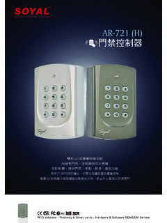
Transcription of SOYAL AR-727 (H-V5)
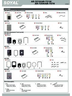
1 SOYALACCESS CONTROL SYSTEM AR-727 (H-V5)V140701 AR-821 RBP1P2P3P4P5P631254 Contents2 User GuideThe communication wires and power line should NOT be bound in the same conduit or t equip reader and lock with the same power supply. The power for reader may be unstable when the lock is activating, that may make the reader standard installation: Door relay and lock use the same power supply, and reader use independent power AWG 22-24 Shielded Twist Pair to avoid star wiring ,CAT 5 cable for TCP/IP supply:Installation1 Products3 Terminal Cables4 Tools5 NoticeConnector Table More details please go download by RelayWire ApplicationWireColorDescriptionLock Relay1 Blue White( )DC24V1 Amp2 Purple White( )DC24V1 AmpLock Relay COM3 White(COM)DC24V1 AmpDoor Contact4 OrangeNegative Trigger InputExit Switch5 PurpleNegative Trigger InputAlarm Relay6 GrayDC24V1 AmpPower7 Thick RedDC 12V8 Thick BlackDC 0 VCable.
2 P1 Wire ApplicationWireColorDescriptionBeeper1 PinkBeeper Output 5V/100mA, LowLED2 YellowRed LED Output 5V/20mA, Max3 BrownGreen LED Output 5V/20mA, MaxDoor Output4 Blue WhiteTransistor Output Max. 12V/100mA (Open Collector Active Low)Wiegand5 Thin GreenWiegand DAT: 0 Input6 Thin BlueWiegand DAT: 1 InputWG Door Contact7 OrangeNegative Trigger InputWG Exit Switch8 PurpleNegative Trigger InputP2 Wire ApplicationWireColorDescription1------2- -----TCP/IP Output3 Orange WhiteNet - TX+4 OrangeNet - TX-5 Green WhiteNet - RX+6 GreenNet - RX-7------P3 Wire ApplicationWireColorDescriptionRS-485 for LiftController1 Thick GreenRS-485(B-)2 Thick BlueRS-485(A+)Cable.
3 P4 Wire ApplicationWireColorDescriptionAnti-Tamp er ApplicationWireColorDescriptionPower1 RedDC 12V OutputSecurity trigger signal 2 PurpleSecurity trigger signal OutputArming3 Red WhiteArming OutputDuress4 Yellow WhiteDuress OutputP6 Wire ApplicationWireColorDescriptionTTL Port 1 BlackDC 0V2 YellowTX3 WhiteTE4 OrangeRX5 RedDC 5V6------Cable: CN11(Optional:Lift Control w/ AR-725L485) / CN9 P7 Cable:Cable:Cable:Cable:Attach the water proof strip to the mounting the cables from the square hole of the mounting a screwdriver to screw the base onto the wall. Connect the terminal cables to the body and attach the body to the mounting the covers with the Allen key and screws (accessories supplied).
4 Turn on the power, the LED will light and hear the beep sound, you will see "Ready"" on LCD proof Strip654321P7CN11 OptionalOptionalOptional654321P9CN987654 321P2CN5321P5CN387654321P1CN421P4CN67654 321P3CN74321P6CN87654321P8CN18 Main PCBLCD-PCBWire ApplicationWireColorDescriptionHID RF Module1 OrangeANT 12 PurpleANT 23 BlackDC 0V4 RedDC 5V5 BlueWiegand DAT: 1 Input6 GreenWiegand DAT: 0 Input7 White --Cable: CN18 (Optional:HID ProxII RF Module)P8P9V140701 PWRERR02/2414 : 49 : 04 FRIDuty : 0 PWRERR02 2414 : 49 : 04 FRIDuty : 0 LCD Access ControllerFront Panel & IndicatorConnect to Electric BoltWiring DiagramEXIT12345678E12 VGNDExit BoltController RTEPOWER12 VDCPOWER12 VDCM agnet LockConnect to Magnet Lock Connect to Electric StrikeConnect to Door RTEPOWER12 VDCPOWER12 VDCE lectric Strike1.
5 System will automatically exit from Programming Mode when inactivating for 30 LED status indicates controller s mode and status. OK (green) blinking constantly when operates in Programming Mode or flashing an existed card in card learn mode, it comes 2 beeps warning and LCD panel displays Same Card: user address / card number Error (red) invalid card with 2 beeps warning and LCD panel displays Card Number Err! or in anti-pass-back mode, when violates the access, it comes one beep warning and LCD panel displays Anti-pass Error!
6 Arming (green) arming on status Alarm (red) any abnormal condition occurs3. Keypad will be locked up 30 sec. when constantly entering incorrect pin code or master Maximum error in[ut of pin code and master code can be changed via the software 701 Server (default: 5 times)Power(Green)Alarm(Red)Alarm(Green) OK(Green) Error(Red)In processing(Green) Networking : / and interactively flash between the Month and DAY. [ ] 02/24 02 24 Stand-alone : No flashing [ ] 02/24( Reference to picture)If any fire emergency, the people can escape by press a switch to open all StrikeElectric BoltFire EmergencyTransistorIN4007 TransistorIN4007 Magnet Lock12345678 Door POWER12 VDCPOWER12 VDCA larmRelay Outpot Module Door CONTROL SYSTEM AR-727 (H-V5)]
7 V140701 0WG 112 VGND1234567812345612 VGNDExit Switch12 VGNDP2P1 BZRLEDGLEDDoor OutputWG 0WG 1WG-DSWG-PB78 EXIT123456781 2 Controller ReaderRTEPOWER12 VDCPOWER12 VDCPOWER12 VDCPOWER12 VDCDoor ContactStrengthen security with AR-721 RBElectric BoltElectric BoltConnect to ReaderAccess programming mode Add/Delete Add -> RF-Learn Input 5-digit user address Input Tag Units(pcs) Close Tag into RF Area If adding a batch of Sequential tags, please input Tag Units(pcs) in the quantity of the tags and present the tag with the lowest card code to the access Tag by RF Learn FunctionTag InformationSITE CODECARD CODESITE CODECARD CODEA dding and Deleting Tag User capacity.
8 16384 (00000~16383)Access programming mode Add/Delete Add -> Card ID Input 5-digit user address Input Site Code Input Card Code11 Adding Tag by Tag IDAccess programming mode Add/Delete Delete -> Addr Input Starting address Input Ending address15 Deleting User AddressAccess programming mode User Setting Access Mode Input User Address 0: Invalid; 1: Card ; 2: Card or PIN; 3: Card & PIN22 Setting up the access modeAccess programming mode Add/Delete Delete -> ID # Input Site Code Input Card Code16 Deleting Tag by Tag IDD.
9 PIN CodeC. Initial setupAccess programming mode User Setting Password Input 5-digit user address Input 4-digit PIN (0001~9999) Succeeded Or via 701 Client set it on Users screen 21 Node ID of Reader SettingAccess programming mode Parameters[1] Node ID Input New Node ID : 1~254 (default value:001) Main Door Number : 0~255 WG1 Door Number : 0~255 Show UID (0=No,1=WG,2=ABA,3=HEX) Enable DHCP(0:No,1:En,2=Exit) Succeeded31 Language SettingAccess programming mode To ols Language EN Succeeded Initial Enable Voice Module (supporting version : F/w Ver or later)Hardware settingAccess programming mode To ols Ext.
10 Comm Port Voice5 Software Setting701 Server orProgrammingB. Entering and Exiting Programming ModeChanging the Master CodeAccess programming mode To ols Master Code Input the 6-digit new master code Succeeded52A. Keyboard Lock/ UnlockLock/ UnlockPress and , and at the same time to lock keyboard. Press again to 123456 or PPPPPP[ ] The Default Value= 123456. If already changed the Master Code= 876112, input 876112 Access programming entering no instruction within 30 sec., it will automatically leave the programming the repeatedly Quit or Quit and Arming (Please refer to alarm / arming setting)67E.