Transcription of SP400 Electropneumatic Smart Positioner - Spirax Sarco
1 IM-P343-37 CH Issue 11SP400 Electropneumatic Smart PositionerInstallation and Maintenance InstructionsIM-P343-37CH Issue Index2. Safety information3. Technical information4. Options5. Installation6. Electrical connections7. Quick start procedure8. Programming flow chart9. Programming and commissioning10. Maintenance11. Default values and program settings12. Glossary of display dataPrinted in the UK Copyright 2010IM-P343-37 CH Issue 121. IndexSection Sub-section General requirements2. Safety Electrical safety requirements information Electromagnetic compatibility Description3. Technical Technical data information Materials Programmable functions4. Options Pressure gauge block Mounting the SP400 Positioner - General informaton Sequence for mounting an SP400 Positioner to5. Installation a linear actuator Sequence for mounting an SP400 Positioner to a rotary actuator Air supply and connections6.
2 Electrical Guidance notes connections Wiring diagrams7. Quick start 2-port valves procedure 3-port valves8. Programming flow chart SET-UP NOW SP400 MENU MANOP9. Programming and AUTOS - automatic autostroke commissioning commissioning SET - setting of valve functions RUN - automatic operation10. Maintenance and Air supply quality troubleshooting Fitting replacement filter plug kit11. Default values and program settings12. Glossary of Main menu display functions display data Sub-menu display functionsIM-P343-37 CH Issue 132. Safety General requirementsThe flawless and safe operation of the SP400 positioners is reliant on proper transportation, storage, installation and commissioning by qualified personnel, proper use and careful to installing, using or maintaining the Positioner , consideration should be given to:- The working Safe Pipeline fluid System SP400 Positioner should be mounted with sufficient space to allow opening of the hinged cover and to provide access for electrical and air connections.
3 When fitting to an actuator, ensure that the Positioner will not be exposed to an ambient temperature outside the range of -10 C to +80 C. The Positioner enclosure is rated to IP65 (see BS EN 60534-1 1998). Electrical safety requirementsThe SP400 is a class III product which must only be powered from Safe Extra Low Voltage (SELV) sources whether by virtue of a 4 - 20 mA control signal or from a separate power supply. Similarly all signal circuits connected to an options board must operate within the confines of SELV systems. All associated wiring must be separated from other wiring containing hazardous Electromagnetic compatibilityThe product complies with the Electromagnetic Compatibility Directive 2004 / 108 / EC according to:- EN 61326-1: 2006- EN 61326-2-3: 2006- EN 55011: 1998 + A1: 1999 + A2: 2002- EN 61000-4-2: 1995 + A1: 1998 + A2: 2001- EN 61000-4-3: 2006- EN 61000-4-4: 2004- EN 61000-4-5: 2006- EN 61000-4-6: 2007- EN 61000-4-11: 2004 This product may be affected by interference if:- The product or its wiring is located near a radio transmitter.
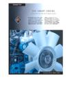
4 The actual separation necessary will vary according to the power of the Cellular telephones or mobile radios are used within approximately one metre of the product or its The wiring is routed alongside power cables subject to high voltage transients or current CH Issue 143. Technical DescriptionThe SP400 Smart valve Positioner is loop powered from a 4 - 20 mA input signal to provide accurate adaptive positional control of pneumatic actuated linear and quarter turn control is maintained through valve position feedback that automatically varies the pneumatic output pressure to overcome the effects of stem friction and flow forces to maintain desired valve position. Indication of valve position is provided through a continuous digital display of % travel. Valve position feedback is retrieved by means of a non contact technology based on Hall effect. The pneumatics are based on piezovalve technology - Therefore, high resolution, high reliability, vibration insensitivity and extremely low air consumption is guaranteed at steady SP400 includes many Smart functions that can be fully programmed through menu driven software using an integral keypad and LCD alphanumeric data.
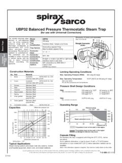
5 The absence of mechanical linkages between valve stem and Positioner , drastically simplifies the mounting procedure and reduces the time required. Moreover the software has been designed to simplify operations as much as possible: commissioning requires just assembling the SP400 to the valve and pressing one button. The SP400 is supplied with a NAMUR standard mounting kit for attachment to yoke or pillar mounted actuators. For quarter turn valves, a mounting kit compliant to VDI / VDE 3845 is 112No. Part1. LCD display 2. Main menu functions with LCD flag indication 3. Signal pressure to actuator4. Gland connection for wiring M20 5. Terminal block 6. Increase value or toggle value key 7. Decrease value or toggle value key 8. Enter key 9. Supply pressure to Positioner 10. Optional pressure gauge block with gauges 11. Spare M20 gland connection for wiring a 4-20 mA retransmission or software switches 12.
6 External earth 13. Internal earth 411109321135678IM-P343-37 CH Issue 15No. Features 1. indicates all is OK 2. ! Indicates a delay in positioning, this disappears when the position is reached 3. Indicates that the value displayed is a percentage 4. Indicates that the value displayed is the input current measured in mA 5. Indicates that the value displayed is a time measured in seconds 6. Indicates that you're accessing the main programming menus 7. Indicates that the Positioner is in manual mode 8. Indicates that the Positioner is running the autocalibration 9. Indicates that you're accessing the SET menu 10. Indicates that the Positioner is in automatic mode 1067895 Fig. Technical dataInput signal range 4 - 20 mA nominalMinimum input signal (loop powered) mAMinimum air supply pressure bar g Maximum air supply pressure 7 bar gAir quality Air supply must be dry, oil and dust free to ISO 8573-1 class 2:3.
7 1 Output pressure 0 to 100% supply pressureStroke range Linear valves 10 mm to 100 mm Quarter turn valves 5 to 120 Action Single action / fail ventOperating temperature -10 C to +80 CMaximum air flow normal m3/h at bar g or normal m3/h at 6 bar gSteady state air consumption Less than normal m3/hAir connections Screwed " NPTC able gland M20 Electrical connections Spring clamp terminals for to mm wireEnclosure rating IP65 Characteristic LinearResolution (maximum) 1%Shipping weight kg2143IM-P343-37 CH Issue MaterialsPart Material FinishCase and cover Die cast aluminium Anti-corrosive paint to RAL5010 Magnet bracket Die cast Programmable functionsAutostroke Automatic commissioning routineValve type 2-port or 3-port% travel Selectable 0 to 100% or 100% to 0% depending on valve / actuator configurationControl action Direct or reverse action (4 - 20 or 20 - 4 mA) OFF range 4-20 mA Split range LOW range 4-13 mA HIGH range 11-20 mA Resets all programmed values to default settingsInput signal Visualisation of input mA signal IM-P343-37 CH Issue 174.
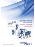
8 Pressure gauge blockAn optional pressure gauge block (Figure 3) can be fitted onto the SP400 Positioner which includes two pressure gauges indicating air supply pressure and output air signal pressure to the actuator. The pressure gauge block can be retrospectively fitted using 2 off M5 socket head screws. Ensure that the gauge block air connection 'O' rings are correctly located before 3IM-P343-37 CH Issue 185. Mounting the SP400 Positioner - General informationPreliminary check of valve and actuator assembly - A preliminary check should be carried out on the valve and actuator assembly prior to mounting and commissioning the SP400 Positioner to confirm smooth movement of the stem. This can be performed by providing an air supply directly from a filter/regulator to the actuator. The air supply pressure should be gradually increased to progressively move the stem through its full travel.
9 Any friction or jerky movement of the stem should be investigated prior to commissioning the The SP400 is supplied with a NAMUR standard fixing kit for linear actuators (yoke or pillar) or with a VDI / VDE 3845 compliant mounting kit for rotary The SP400 has an enclosure rating of IP65 and should be installed in a location that will not exceed its ambient temperature limits of -10 C minimum and +80 C maximum. Before fitting and commissioning the SP400 Positioner ensure that the valve and actuator are correctly assembled. Refer to the valve and actuator Installation and Maintenance Instructions for details. IM-P343-37 CH Issue Loosely attach the magnet bracket (2) to the valve / actuator connector (refer to Figures 4 and 5). Be sure it is positioned horizontally (as shown in Figure 5). Fig. 4 Pillar mounting kit for a linear actuatorFig. 5 Yoke mounting assembly for a linear Sequence for mounting an SP400 Positioner to a linear actuator22IM-P343-37 CH Issue Slide the bracket (2) to the left or to the right (Figure 6) till the correct position is achieved.
10 If you re using a Spirax Sarco actuator the correct position is impressed on the magnet bracket (Figure 7). If you re not using a Spirax Sarco actuator, slide the bracket till the distance 'A' between the center of the magnet and the inner side of the mounting plate is 25 mm (Figure 8). Fig. 8 ADistance between the mounting plate and magnetFig. 7 Bracket markingsFig. 6 Assembled2 Mounting plateBracketCenterof themagnetPN1000PN9000IM-P343-37 CH Issue Loosely attach the Positioner mounting plate to the actuator as shown in the following pictures: for the pillar actuator (Figure 9), and for the yoke actuator (Figure 10). Fig. 9 Pillar actuator assemblyPillar actuatorMounting Yoke actuator assemblyYoke actuatorMounting Locate the protection plate onto the back of the SP400 Positioner housing and fix in place (Figures 11 and 12).Protection plateFig. 11 AssembledAssembledAssembledFig.