Transcription of SP481E SP485E DS - exar.com
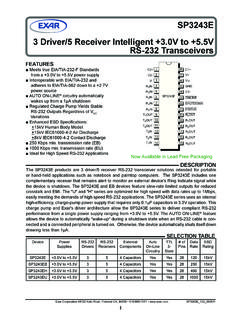
1 enhanced low power half - duplex RS-485 Transceivers SP481E / SP485E1/9 REV 5V only low power BiCMOS Driver / receiver enable for multi-drop configurations low power shutdown mode ( SP481E ) enhanced ESD specifications: 15kV Human Body Model 15kV IEC61000-4-2 Air Discharge 8kV IEC61000-4-2 Contact Discharge Available in RoHS compliant, lead free SP481E and SP485E are a family of half - duplex transceivers that meet the specifications of RS-485 and RS-422 serial protocols with enhanced ESD performance. The ESD tolerance has been improved on these devices to over 15kV for both Human Body Model and IEC61000-4-2 Air Discharge Method.
2 These devices are pin-to-pin compatible with MaxLinear s SP481 and SP485 devices as well as popular industry standards. As with the original versions, the SP481E and SP485E feature Maxlinear s BiCMOS design allowing low power operation without sacrificing performance. The SP481E and SP485E meet the requirements of the RS-485 and RS-422 protocols up to 10 Mbps under load. The SP481E is equipped with a low power shutdown DiagramOrdering Information - Back PageSP481E and SP485 ERO 1RE2DE 3DI 4 VCC8B7A6 GND5 DRSP481E / SP485E2/9 REV Maximum RatingsThese are stress ratings only and functional operation of the device at these ratings or any other above those indicated in the operation sections of the specifications below is not implied.
3 Exposure to absolute maximum rating conditions for extended periods of time may affect .. Voltages Logic .. to (VCC + ) to (VCC + ) .. 15 VOutput Voltages Logic .. to (VCC + ) Drivers .. 15V to (VCC + )Storage Temperature ..-65 C to +150 CPower Dissipation8-pin NSOIC ..550mW (derate C above +70 C)Electrical CharacteristicsTAMB = TMIN to TMAX and VCC = 5V 5% unless otherwise / SP485E Driver DC CharacteristicsDifferential output voltageVCCVU nloaded; R = ; Figure 1 Differential output voltage2 VCCVWith load; R = 50 (RS-422); Figure 1 Differential output load; R = 27 (RS-485); Figure 1 Change in magnitude of driver differential output voltage for complimentary = 27 or R = 50 ; Figure 1 Driver common-mode output voltage3VR = 27 or R = 50.
4 Figure 1 Input high to DE, DI, REInput low to DE, DI, REInput current 10 AApplies to DE, DI, REDriver short circuit current VOUT = HIGH 250mA-7V VO 12 VDriver short circuit current VOUT = LOW 250mA-7V VO 12 VESD RatingsHBM - Human Body Model (A and B pins).. 15kVHBM - Human Body Model (All other pins).. 3kVIEC61000-4-2 Air Discharge (A and B pins).. 15kVIEC61000-4-2 Contact Discharge (A and B pins).. 8kVSP481E / SP485E3/9 REV Characteristics (Continued)TAMB = TMIN to TMAX and VCC = 5V 5% unless otherwise / SP485E Driver AC CharacteristicsMaximum data rate10 MbpsRE = 5V, DE = 5V.
5 RDIFF = 54 , CL1 = CL2 = 100pFDriver input to output, tPLH3060nsSee Figures 3 & 5, RDIFF = 54 , CL1 = CL2 = 100pFDriver input to output, tPLH (SP485 EMN ONLY)3080nsDriver input to output, tPHL3060nsSee Figures 3 & 5, RDIFF = 54 , CL1 = CL2 = 100pFDriver input to output, tPHL (SP485 EMN ONLY)3080nsDriver skew510nsSee Figures 3 and 5, tSKEW = |tDPHL - tDPLH|Driver rise or fall time1540nsFrom 10%-90%; RDIFF = 54 CL1 = CL2 = 100pF; See Figures 3 and 6 Driver enable to output high4070nsCL = 100pF, See Figures 4 and 6, S2 closedDriver enable to output low4070nsCL = 100pF, See Figures 4 and 6, S1 closedDriver disable time from high4070nsCL = 100pF, See Figures 4 and 6, S2 closedDriver disable time from low4070nsCL = 100pF, See Figures 4 and 6, S1 closedSP481E / SP485E Receiver DC CharacteristicsDifferential input VCM 12 VDifferential input threshold (SP485 EMN ONLY)
6 VCM 12 VInput hysteresis20mVVCM = 0 VOutput voltage = 200mV, IO = -4mAOutput voltage = 200mV, IO = 4mAThree-state ( high impedance) output current 1 VO ; RE = 5 VInput resistance1215k -7V VCM 12 VInput current (A, B); VIN = = 0V, VCC = 0V or , VIN = 12 VInput current (A, B); VIN = = 0V, VCC = 0V or , VIN = -7 VShort circuit current795mA0V VO VCCSP481E / SP485E Receiver AC CharacteristicsMaximum data rate10 MbpsRE = 0V, DE = 0 VReceiver input to output 2045100nstPLH ; See Figures 3 & 7, RDIFF = 54 , CL1 = CL2 = 100pFReceiver input to output 2045100nstPHL.
7 See Figures 3 & 7, RDIFF = 54 , CL1 = CL2 = 100pFDifferential receiver skew|tPHL - tPLH|13nsRDIFF = 54 , CL1 = CL2 = 100pF, See Figures 3 and 7 Receiver enable to output low4570nsCRL = 15pF, Figures 2 S1 ClosedReceiver enable to output high 4570nsCRL = 15pF, Figures 2 S2 ClosedReceiver Disable from low 4570nsCRL = 15pF, Figures 2 S1 ClosedReceiver Disable from high 4570nsCRL = 15pF, Figures 2 S2 ClosedSP481E / SP485E4/9 REV Characteristics, ContinuedTAMB = TMIN to TMAX and VCC = 5V 5% unless otherwise Shutdown TimingTime to shutdown50200600nsRE = 5V, DE = 0 VDriver enable from shutdown to output high40100nsCL = 100pF; See Figures 4 and 6; S2 ClosedDriver enable from shutdown to output low40100nsCL = 100pF; See Figures 4 and 6; S1 ClosedReceiver enable from shutdown to output high3001000nsCL = 15pF; See Figures 2 and 8; S2 ClosedReceiver enable from shutdown to output low3001000nsCL = 15pF; See Figures 2 and 8.
8 S1 ClosedPower RequirementsSupply voltage currentNo load 900 ARE, DI = 0V or VCC; DE = VCC600 ARE = 0V, DI = 0V or 5V; DE = 0 VShutdown mode ( SP481E )10 ADE = 0V, RE = VCCE nvironmental and MechanicalOperating Temperture Commercial (_C_)070 C Industrial (_E_)-4085 C (_M_)-40125 CStorage Temperature-65150 CPackage NSOIC (_N) SP481E and SP485E Pinout (Top View)Pin FunctionsPin NumberPin NameDescription1 ROReceiver output2 REReceiver output enable active LOW3 DEDriver output enable active HIGH4 DIDriver input5 GNDG round connection6 ANon-inverting driver output / receiver input7 BInverting driver output / receiver input8 VCCP ositive supply Vcc 1RE2DE 3DI 4 VCC8B7A6 GND5 DRSP481E / SP485E5/9 REV CircuitsFigure 1: RS-485 Driver DC Test Load CircuitFigure 2: Receiver Timing Test Load CircuitFigure 3: RS-485 Driver/Receiver Timing Test CircuitFigure 4.
9 Driver Timing Test Load #2 CircuitABRRVODVOC1k 1k CRLR eceiverOutputS1S2 Test PointVCCCL115pFROABABDICL2RL500 CLOutputUnderTestS1S2 VCCS witching Waveforms+3V0 VDRIVER INPUTABDRIVEROUTPUTVO+DIFFERENTIALOUTPUT VA VB0 VVO 1 MHz; tR 10ns; tF 10nsVO1/2VO1/2 VOtPHLtSKEW = |tDPLH - tDPHL|tDPLHtDPHLF igure 5: Driver Propagation DelaysSP481E / SP485E6/9 REV 6: Driver Enable and Disable TimesFigure 7: Receiver Propagation DelaysFigure 8: Receiver Enable and Disable TimesSwitching Waveforms (Continued)+3V0 VDE5 VVOLA, = 1 MHz; tR < 10ns; tF < 10nsVOHA, normally LOWO utput normally = 1 MHz; tR 10ns; tF 10nsOUTPUTVOD2+VOD2 A B0V0 VtPLHINPUT + = 1 MHz; tR 10ns;tF normally LOWO utput normally HIGHVILVIHRRE SP481E / SP485E7/9 REV SP481E and SP485E are half - duplex differential transceivers that meet the requirements of RS-485 and RS-422.
10 Fabricated with an Maxlinear proprietary BiCMOS process, this product requires a fraction of the power of older bipolar RS-485 standard is ideal for multi-drop applications and for long-distance interfaces. RS-485 allows up to 32 drivers and 32 receivers to be connected to a data bus, making it an ideal choice for multi-drop applications. Since the cabling can be as long as 4,000 feet, RS-485 transceivers are equipped with a wide (-7V to 12V) common mode range to accommodate ground potential differences.