Transcription of Spandrel panels FINAL - 04.01 - NHBC
1 CURTAIN WALLING FORMED FROMSTACKED WINDOW ARRANGEMENTS EXXON page 1 of 9 MARKING OF SAFETY GLASS XXXX 2015 TECHNICAL GUIDANCESPANDREL panels TO COLD ROOFS /25 January 2018 (First Issue) NHBC NHBC House, Davy Avenue, Knowlhill, Milton Keynes, Bucks MK5 8 FPTel: 0344 633 1000 Fax: 01908 747 255 Spandrel panels are generally factory-made, transported to site in one or more sections, and craned into position on to timber framed or masonry support walls. Panel framing is usually formed from vertical studs at 600mm centres, with head and soleplates. Typical timber sizes are:89 x 38mm or 97 x 47mm with nailed connections or72 x 47mm where joints are plated, as in trussed rafter plated panels should be designed by the manufacturer in accordance with the building designer s details and requirements and manufactured in accordance with guidance from the Structural Timber Association ( ) or Trussed Rafter Association ( ).
2 The top of party wall panels should be slightly lower than the level of adjacent trusses, to allow the trusses to de ect on application of the roof tiles, without causing hogging of the tiles over the panel. Gable panels are installed level with the top of the trusses with ush roof verges; or to underside of gable ladders with boxed wall panels require tying back into the roof structure on BOTH sides, so that they remain in place in the event of the roof on one side burning away. Gable Spandrel panels must resist wind loads acting on the gable end walls and any loads from applied cladding, tile hanging. These loads are transmitted through the panel to the roof structure via lateral restraints. In accordance with masonry codes, wall ties to masonry cladding should be increased in number at the top of a wall.
3 Wall ties should also be increased at potential slip planes, horizontal cavity tray locations. Detail 10 below shows where wall tie frequency should be impervious weather protection, polythene sheeting, should be removed once the roof is watertight, su cient to allow the panel to breathe, identify stud positions for xing restraints, and checking for any damage during erection. Breathable protective membrane may require removal for inspection if there are signs of trapped moisture or damage to the panel. Where membranes are retained, on gable panels , the position of the studs should be marked on the membrane for xing of wall ties. Which factors should be taken into account when designing and installing Spandrel panels over party walls and gable walls with cold roof voids?1) GENERAL CONSIDERATIONS2) LATERAL RESTRAINT3) FIRE STOPPINGS pandrel panels require lateral restraint at rafter level and along the base of the panel.
4 Tall panels may also require lateral restraint in line with any intermediate longitudinal bracing to the roof trusses. Lateral restraint can be provided by:- timber members ( the longitudinal bracing secured to the Spandrel with timber ledgers/noggings), xed into at least two studs within the panels , - metal restraint straps xed to the panel and to noggings, or timber bracing xed between or across the trusses. Multiple xings into narrow studs, 38mm wide, at the end of restraint straps, should be avoided by xing the straps into timber ledgers, xed across and into two studs within the panel - see stopping is required between the top of the party wall Spandrel panel and the roof covering, and between the Spandrel and the masonry supporting wall. This is typically achieved with exible rock bre mineral quilt.
5 The re stopping should extend into any boxed eaves in the form of re-resisting board or wired rock bre quilt, screwed ornailed in place (see diagram in NHBC Standards clasue ).6. 1/ 25 2015 20147. 2/ 25 Jan 2018 TECHNICAL GUIDANCE page 2 of 9 NHBC NHBC House, Davy Avenue, Knowlhill, Milton Keynes, Bucks MK5 8 FPTel: 0344 633 1000 Fax: 01908 747 255 The building designer/architect should agree re protection requirements with the NHBC building control surveyor for the project (or local authority building control in Scotland and Northern Ireland), particularly for panels clad with weatherboarding or tile hanging, where lack of re resistance to external face can be a ected by re spread from below. Requirements should be clearly illustrated on the working party wall Spandrel panels should provide 60 minutes re protection, which can be achieved with two layers of plasterboard on both sides of the framing.
6 plasterboard joints in each layer and between layers should be made over a stud or nogging and staggered. With twin leaf Spandrel panels the same re protection is applied to one side of each leaf, usually the side facing the roof , single layer board drylining may be used if supported by suitable test reports to show compliance with the re and sound protection to gable end Spandrel panels is dependent on the dwelling type, house or at, its height, and distance from relevant boundaries. Based on Approved Document B1 (England) and 100mm thick masonry tied to the gable Spandrel panel, the following re protection generally applies:i) Three storey houses and two storey spread of re (Requirement B4) may apply if the building is close to a boundary and the area of the gable wall is larger than the allowable unprotected area for the plot.
7 Where a 30 minute period of re resistance is needed, an unlined Spandrel panel with 100mm masonry wall is considered to meet this ) Houses and ats with height exceeding (i) spread of re (Requirement B4) may apply if the building is close to a boundary and the area of the gable wall is larger than the unprotected area . A 60 minute period of re resistance is needed. An unlined Spandrel panel and 100mm masonry wall is NOT considered su cient to meet this period. Consideration should be given to re protection of the Spandrel panel, such as a lining to the internal face of the butt joints should maintain the required re protection. This can be achieved by covering the joint with strips of plasterboard to the same thickness as used on the main panel - see detail below. Other panel to panel jointing methods may be accepted if supported by an appropriate re test report.
8 Jointing methods which rely on the use of intumescent sealants are di cult to inspect for correct installation, so should generally be ) FIRE PROTECTION5) ACOUSTICS6) TYPES OF Spandrel panels AND WORKED EXAMPLESThe Spandrel panel should meet the sound insulation requirements set out in the National Building way of achieving this is to follow the guidance in Robust Details; the guidance in this document follows that approach. Designs which do not adopt Robust Details will require sound testing on types of Spandrel panel covered by this guidance are as follows: Type One - Twin leaf panels supported on a timber framed party wall Type Two - Single leaf panel supported on a timber framed party wall Type Three - Single leaf panel supported on a masonry party wall Type Four - Single leaf panel supported on a timber framed gable wallType Five - Single leaf panel supported on the inner leaf of a masonry cavity gable wall Type Six - Single leaf panel supported on the outer leaf of a masonry cavity gable wall The following drawings show commonly accepted practice and are included to help illustrate the points described in this guidance.
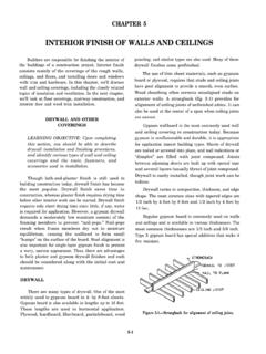
9 The actual design and restraint of the panels may vary depending on the site design, manufacture and provision of lifting points for the erection of the Spandrel panels should be undertaken by the panel manufacturer. The restraint of the panels , once erected, should be designed by the building designer/architect to suit the structural and re requirements for each project. Erection procedures and temporary restraint requirements are outside the scope of this 1/ 25 2015 20147. 2/ 25 Jan 2018 TECHNICAL GUIDANCE page 3 of 9 NHBC NHBC House, Davy Avenue, Knowlhill, Milton Keynes, Bucks MK5 8 FPTel: 0344 633 1000 Fax: 01908 747 255 ledger to support plasterboard edge and for connection of lateral restraint binderlateral restraint (see detail 1)lateral restraint (see detail 2)BBfireproofing (see detail 3)Single leaf Spandrel panel supported on a timber framed party wallTYPE TWOpanel to panel joint (see section B-B)insulation to avoid cold bridging unless shownby calculation as not requiredinsulation to avoid cold bridging unless shownby calculation as unecessarycontinuous ledger to support plasterboard edge and for connection of lateral restraint binderfireproofing (see detail 3)lateral restraint (see detail 1)lateral restraint (see detail 2)Twin leaf Spandrel panel supported on a timber framed party wall (generic twin wall system)TYPE ONEAA panel-to-panel joint (see section A-A)6.
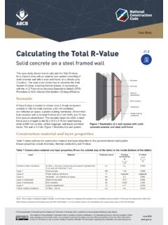
10 1/ 25 2015 XXX 20147. 2/ 25 Jan 2018 TECHNICAL GUIDANCE page 4 of 9 NHBC NHBC House, Davy Avenue, Knowlhill, Milton Keynes, Bucks MK5 8 FPTel: 0344 633 1000 Fax: 01908 747 255 ledger to support plasterboard edge and for connection of lateral restraint binderlateral restraint (see detail 1)lateral restraint (see detail 4)BBlateral restraint (see details 4 & 5)300mm min.(for sound-proofing)cavity insulation to depth of ceiling insulation to reduce cold bridgingcavity closer and mineral wool quiltfireproofing (see detail 3)panel-to-panel joint (see section B-B)Single leaf Spandrel panel supported on a masonry party wallTYPE THREES ection-view A-A of joint in Spandrel panelcover strips of double layer plasterboard across butt joint between panelsfirst and second layers of plasterboard individually fixed into each stud with screws at 300mm max.