Transcription of SPECIFICATION AND INSTALLATION INSTRUCTIONS
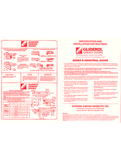
1 INSTALLATION INSTRUCTIONS - Series A & AA Roller doors, Page-1 SPECIFICATION AND INSTALLATION INSTRUCTIONS Made under license Aust Patent No. 413178 and Patent Application No. 483904 SERIES A & AA CONTINUOUS CURTAIN ROLLER DOORS For all popular sizes of garage openings Your Gliderol Roller door is designed to highest engineering standards and manufactured from high quality materials. If it is installed in accordance with the INSTRUCTIONS given in this manual it will give many years of service with a minimum of maintenance. Warning! No guarantee will be given or responsibility accepted by the manufacturer if the door is not installed by an authorised Gliderol Installer. GLIDEROL GARAGE DOORS 32 Jacobsen Crescent Holden Hill SA 5088 Phone (08) 8261 9633 Fax (08) 8261 9700 Branches Victoria: Gliderol Garage Doors, 23 Kitchen Rd, Dandenong, VIC 3175. Phone: 03 97935455 Fax: 03 9706 8492 NSW: Gliderol Garage Doors, 45 Sammut St, Smithfield, NSW 2164.
2 Phone: (02) 9725 1033 Fax: (02) 9725 1115 Queensland: Gliderol Garage Doors, 241 Elliott road Banyo, QLD 4014. Phone: 07 3260 9000 Fax: 07 3260 9055 Western Australia: Gliderol Garage Doors, 21 Prindiville Dr, Wangara, WA 6065. Phone: 08 94093000 Fax: 08 94093200 New Zealand: Gliderol Garage Doors, 12 Cape Hill Road, Pukekohe, Auckland NZ. Phone: 09 835 0211 Fax: 09 237 0440 UK: Gliderol Garage & Industrial Doors Ltd. 1 Davy Drive, North West Industrial Estate, Peterlee Co, Durham, SR8 2JF UK. Phone: 1915 18 0455 Fax: 1915 18 0548 PREPARATION Remove all parts. THE WRAPPING HOLDING THE DOOR MUST NOT BE CUT AT THIS STAGE. The doors are positioned inside the opening and, therefore, overlap the opening on each side by 25mm for series A and 50mm for Series AA doors. A minimum of 75mm is required between the opening and the side wall for Series A doors, 150mm for Series AA. Before commencing, measure both the opening and the door curtain and mark the overlap on the wall to facilitate the fixing of brackets and guides.
3 PLEASE FOLLOW THE INSTRUCTIONS CAREFULLY 12 AFFIXING MOUNTING BRACKETS The minimum headroom required between the underside of the rafters and the top of the opening is 400mm for Series A doors and 450mm for Series AA doors. Firmly secure one of the mounting brackets with appropriate fixings for the material you are fixing to, (Refer table for maximum pull out strength requirements while selecting fixings). It is important that the outside face (smooth side) of the angle brackets faces the side wall of the garage. The clearance on either side between the door curtain and mounting brackets is 10mm minimum and 100mm maximum. (Manual Doors Only) The top of the bearing surface of the mounting brackets should be 150mm from the top of the opening, and 250mm minimum from the underside of the rafters. In the event of shallower headroom, the 250mm dimensions must be maintained.
4 Shallower headroom s down to 300mm can be maintained, but will result in the underside of the rolled up door showing when the door is in the open position. The second mounting bracket should then be positioned. The use of a line level or spirit level and straight edge is recommended as IT IS VITAL THAT THE BRACKETS ARE EXACTLY LEVEL WITH EACH OTHER, otherwise the door will not sit square. The minimum 250mm dimension must be maintained. Fig- 1 INSTALLATION INSTRUCTIONS - Series A & AA Roller doors, Page-2 POSITIONING THE DOOR First make sure the axle is centered within the curtain roll. Place the rolled up door on the mounting brackets and centre the axle approximately 250mm from the front wall, ensuring that the door iscentralized with the opening.
5 If the side clearance for the axle is insufficient, cut EACH END of the axle. IT IS IMPORTANT THAT THE AXLE IS NOT CUT TOO SHORT. UNROLLING THE DOOR Hold the door in its tensioned position and remove the wrapping which holds the door in a roll. It is important that the door is held firmly at this stage to prevent loss of tension. Pull the door partly down. THE DOOR MAY HAVE A STRONG TENDENCY TO RISE WHICH, IF UNCONTROLLED, CANCAUSE DAMAGE. Affix the lifting handle in the centre of the aluminium bottom rail and allow the door to rise slowly, the handle acting as a door stop against the lintel. If the lifting handle will not engage the lintel for anyreason, use a piece of soft timber as a chock, approximately 450mm long, and place it between the bottom rail and the drum, as shown, taking care not to damage the door. On Series AA doors only, fit the left and right handed nylon guide stop blocks to the aluminium bottomrail by sliding them beneath the Polyglide wearing strips and securing the gutter bolts, ensuring thehead of the gutter bolt is on the outside of the door.
6 When lifting the Polyglide, ensure that the PVC finned weatherseal remains in position. FIXING THE SIDE TRACKS Carefully remove the wood chock, if used. Ensure that the door curtain is rolled up evenly andcentered on the opening. Should the door be coned due to movement in transit, then the door curtain should be carefully unrolled to its full extent and rolled back evenly before continuing, making sure the curtain is no longerin a coned position. Clean the side tracks with a spirit cleaner. The top of the tracks should be splayed, to ensure the curtain feeds in without obstruction and anyrough edges taken out with a file. The bottom of the side tracks must be at finished floor line. If the floor is slightly out of level, alwayswork from the higher side first. The top of the tracks (splayed end) should be level with the top of thebearing surface of the mounting brackets.
7 Cut one side track to the correct length if necessary, at the bottom. Slide fixing lugs on. Slide the track on to the door curtain, allowing 4mm clearance. Hold the guide in position against thewall and mark the location of the top lug holding screw(For Series A doors only: slide the guide stop between the slots in the guide as shown in fig. 4a and mark the location of the guide stop holding screw in any one of the holes depending upon the best position on the brick). USING A SPIRIT LEVEL TO ENSURE THAT THE SIDE TRACK IS ABSOLUTELY VERTICAL, fix the track in position bymeans of the adjustable lugs and coach screws ensuring that they are evenly spaced, with the bottomlug approximately 200mm from the floor. Similarly, cut the second track to the correct length, if necessary and repeat previous step ensuring that the side track is ABSOLUTELY VERTICAL. Ensure that the door is placed in the correct way round on the brackets.
8 The sketch illustrates the relative position of the bottom rail. Secure the axle to the mounting brackets with the U Bolts. LOCK TIGHTLY using washers under the nuts. Spring tension will be lost if the axle is not firmly clamped. Tension should now be applied to the spring by rotating the door about 11/2 times in a forward direction, as shown. The amount of tension required to give the best operation may vary with individual doors. Final adjustment should be made on completion of the job. 3 4 5 Fig- 3 Fig- 4a Fig- 2a Fig- 2b For series A doors only Fig- 4b INSTALLATION INSTRUCTIONS - Series A & AA Roller doors, Page-3 MAINTENANCE Roller Door Curtain: Gliderol roller door curtain is made up of colorbond prepainted steel which is highly durable and decorative finish. For maintenance regularly wash the curtain by fresh, clean water to enhance its life and maintain attractive finish.
9 If this method does not remove all the dirt adhered on the surface please follow below procedure Wash the surface of the roller door curtain with a mild solution of pure soap or mild non-abrasive kitchen detergent in warm water. Application should be with a sponge, soft cloth or soft bristle nylon brush, and should be gentle to prevent shiny spots. The roller door curtain surface should be thoroughly rinsed with clean water immediately after cleaning to remove traces of detergent. Caution: Never use abrasive or solvent type cleaners like turpentine s, petrol, kerosene, paint thinners to clean roller door surface as it may ruin the paint. Visual Inspection: Conduct visual inspection of mounting brackets, springs, tracks, Guide lugs, fasteners, drive unit cables, weatherseal etc. for any wear and tear at least once in every six months Springs should be lubricated using grease once in six months for proper functioning of the door and locking mechanism should be twice a year with general purpose oil or motor oil.
10 As Polyglide is self lubricated it is important NOT to lubricate the guides. It is advised from time to time to clean the guides with spirit cleaner and polish with car polish. IMPORTANT: DO NOT LUBRICATE GUIDE TRACKS. Door Balance: The roller door should be perfectly balanced for optimum performance and power consumption (for electric operation). Perform door balance test regularly at least once in six months to increase the efficiency of the roller door Fully close the door If the door is operated electrically put it to manual operation by pulling the manual release pin (refer owners manual). Lift the door manually to waist height, say one metre above the floor level you should be able to lift the door with little effort and the door should stay open at that position. If the door does not stay at that position (one metre) implies the door is out of balance. Get the door balanced by a Gliderol authorized service agent.