Transcription of Specification - Day Tank
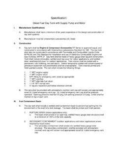
1 Specification : Diesel Fuel Generator Base tanks I. Manufacturer Qualifications A. Manufacturer shall have a minimum of ten years experience in the design and construction of generator base tank systems. B. Manufacturer must be Underwriters Laboratories (UL) listed II. Generator Base Tank Construction A. Generator base tank shall be Engine & Compressor Accessories [SCGBT] [CTDGBT]. [OTDGBT] [GBT] series or approved equal, and constructed in accordance with Underwriters Laboratories Standard UL-142. The generator base tank shall also be constructed in accordance with Flammable and Combustible Liquids Code, NFPA 30; and The Standard for Installation and use of Stationary Combustible Engine and Gas Turbines, NFPA 37. Generator base tank shall be made of heavy gauge steel construction. Include reinforced steel box channel for generator support, with load rating of 4,000 lbs. per gen-set mounting hole location. Two full height gussets shall be provided at gen-set mounting holes.
2 Tank interior shall be coated with a permanent, rust inhibiting, two part epoxy. Interior temporarily coated with solvent-based or petroleum based film rust preventative shall be unacceptable. Tank shall be primed and finish painted outside. III. Generator Base Tank Testing A. Primary tank sections shall be pressurized at 3 psi and leak tested to ensure integrity of generator base weld seams per UL-142 standards. B. Open Top Dikes and Closed Top Dikes shall be hydrostatically tested to ensure integrity of generator base weld seams. Dye penetrant testing shall be unreliable and unacceptable C. Secondary Containment basin shall be pressurized at 3 psi and leak-tested to ensure integrity of generator base weld seams per UL-142 standards. IV. Generator Base Tank Fittings A. The generator base tank shall include the following fittings labeled with adhesive backed metal labels: 1. 1" NPT fuel return fitting 2. 1 " NPT for normal vent (two if Secondary Containment). 3.
3 NPT for emergency vent, sized as appropriate (two if Secondary Containment). 4. 2" NPT for manual fill 5. 1 NPT for level gauge 6. 1" NPT basin drain (tank drain if single wall). 7. 1" NPT for low level float switch 8. 1 NPT fitting for leak detection float switch V. Fuel Level Gauge A. The generator base tank shall include a direct-reading fuel level gauge. VI. Fuel Containment Basin (Double Wall tanks ). A. Generator base tank shall include a welded steel [Open Top Dike] [Closed Top Dike]. [Secondary Containment] containment basin, sized at a minimum of 110% of the tank capacity to prevent escape of fuel into the environment in the event of a tank leakage. VII. Leak Detection System (Double Wall tanks ). A. A fuel containment basin leak detector float switch shall be provided. VIII. Generator Base Tank Venting A. NORMAL VENTING. 1. Normal venting shall be sized at 1-1/4" NPT in accordance with The American Petroleum Institute Standard No. 2000, for venting atmospheric and low pressure storage tanks .
4 Tank shall be provided with atmospheric (normal) vent cap with screen. 2. A second normal vent fitting shall be provided for the interstitial space on Secondary Containment tanks . B. EMERGENCY VENTING. 1. The emergency vent NPT fitting shall be sized to accommodate the total capacity of both normal and emergency vents, and not less than that derived from NFPA 30, Table 2-8, based on wetted surface area of the tank (calculated based on 100% of primary tank). A UL Listed emergency pressure relief vent cap shall be furnished. The vent shall be pressure operated. Opening pressure shall be psig; full opening pressure shall be psig. Limits shall be marked on top of each vent. 2. A second UL Listed emergency vent fitting shall be provided for the interstitial space on Secondary Containment tanks .