Transcription of Specification of MEMS silicon microphone
1 Best sound electronics F1-(A4)CMOE-I110TM42-4P Wide Band Compact OMNI-DIRECTIONAL Top PORT F1-(A4)CMOE-I110TM42-4P F1-(A4)CMOE-I110TM42-4P Best sound electronics F1-(A4)CMOE-I110TM42-4P 2 1. INTRODUCTION Analog mems microphone Single Mode Top Port Type - Sensitivity is Typical -42dBV/Pa Wideband Frequency - 2dB at 50 ~ 8000 (reference page 5) Omni-directional RF Shielded - with embedded Ground Compatible with Sn/Pb and Halogen-free solder process RoHS compliant SMD reflow temperature of up to 260 C for over 30 seconds 3.
2 MODEL NO. F1-(A4)CMOE-I110TM42-4P 2. APPLICATIONS Smartphones Ear-sets, Bluetooth Headsets Tablet Computers Wearable Devices Electrical Appliances Voice Recognition Systems of Appliances 4. GENERAL microphone SPECIFICATIONS Test Condition : 23 2 C, Room Humidity = 55 20 %, VDD= , unless otherwise noticed. Parameter Conditions Min Typ Max Units Directivity Omni-directional Operating Voltage (Vdd) - V Sensitivity Change across Voltage Vdd= ~ No Change dB Best sound electronics F1-(A4)CMOE-I110TM42-4P 3 5. ELECTRO-ACOUSTIC CHARACTERISTICS Test Condition : 23 2 C, Room Humidity = 55 20 %, VDD= , unless otherwise noticed.
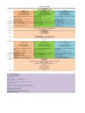
3 Parameter Conditions Min Typ Max Units Sensitivity (S) 94dB SPL at 1kHz, 0 =1V/Pa -45 -42 -39 dBV/Pa Output Impedance (ZOUT) 94dBSPL at 1kHz - - 350 Current Consumption Vdd= ~ 50 70 110 Signal to Noise Ratio (SNR) 94dBSPL at 1kHz, A-weighted (20 ~20 ) - 59 - dB(A) Equivalent Input Noise (EIN) 94dBSPL at 1kHz, A-Weighted (20 ~20 ) - 35 - dB(A)SPL Frequency Response 94dBSPL, within 2dBr (0dBr = dBV/Pa at 1 ) 50 - 8000 94dBSPL, within 3dBr (0dBr = dBV/Pa at 1 ) 8000 - 15000 Power Supply Rejection (PSR) 100mVp-p square wave at 217Hz, Vdd= , A-weighted - -85 - dBV(A) Power Supply Rejection Ratio (PSRR) 200mVp-p sine wave at 1kHz, Vdd= - - dB Total Harmonic Distortion (THD) 94dB SPL at 1kHz - - % 120dB SPL at 1kHz - - 123dB SPL at 1kHz - - 125dB SPL at 1kHz - - Acoustic Overload Point (AOP) THD>10% at 1kHz 128 130 - dBSPL DC Output Voltage Vdd= ~ V Start-up time - - 100 ms Best sound electronics F1-(A4)CMOE-I110TM42-4P 4 Dotted section Represents microphone External Gain = -R1/R2 (Set by customer) Vdd (Pin1)
4 GND (Pin2, 3) Vout_P (Pin3) Vout (Pin4) R2 Vref R1 7. RECOMMENDED INTERFACE CIRCUIT (a) mems Unit : Membrane & Back Plate (transmit the electric signal modified from sound signal to ASIC) (b) ASIC : Impedance converter (Mechanical Signal Electric Signal) (c) Vdd : Power Supply (Operation of ASIC) (d) Rectifier Capacitor : Removed Direct Current Factor (e) Output : Output Signal of microphone s Sensitivity (f) GND : Ground 6. MEASUREMENT CIRCUIT VP mems Unit AMP Pin1 Pin4 Pin2, 3 1 uF Output GND MIC Case (b) (d) Best sound electronics F1-(A4)CMOE-I110TM42-4P 5 Far Field Measurement Condition Temperature : 23 2 C Supply Voltage : Acoustic stimulus : 1Pa ( 94 SPL at 1 ) at 50 from the loud-speaker.
5 The loud-speaker must be calibrated to make a flat frequency response input signal. Position : The frequency response of microphone unit measured at 50 from the loud-speaker. 8. TYPICAL FREQUENCY RESPONSE CURVE(FAR FIELD) Frequency Mask Specification Frequency [Hz] Lower Limit [dBr] Upper Limit [dBr] Note 50 ~ 1000 -2 +2 0dBr = dBV/Pa at 1 1000 0 0 1000 ~ 8000 -2 +2 8000 ~ 15000 -3 +3 Note : Band Frequency Range 1. Narrow Band : 300 ~ 2. Wide Band : 100 ~ 7 3.
6 Super Wide Band : 50 ~ 14 Best sound electronics F1-(A4)CMOE-I110TM42-4P F1-(A4)CMOE-I110TM42-4P 6 SMD Type PCB design & Pin size can be changed by model No. 9. MECHANICAL CHARACTERISTICS Lettering 07 14 Version Year Week E : Engineering Sample P : Pre-Production M : Mass Production